u
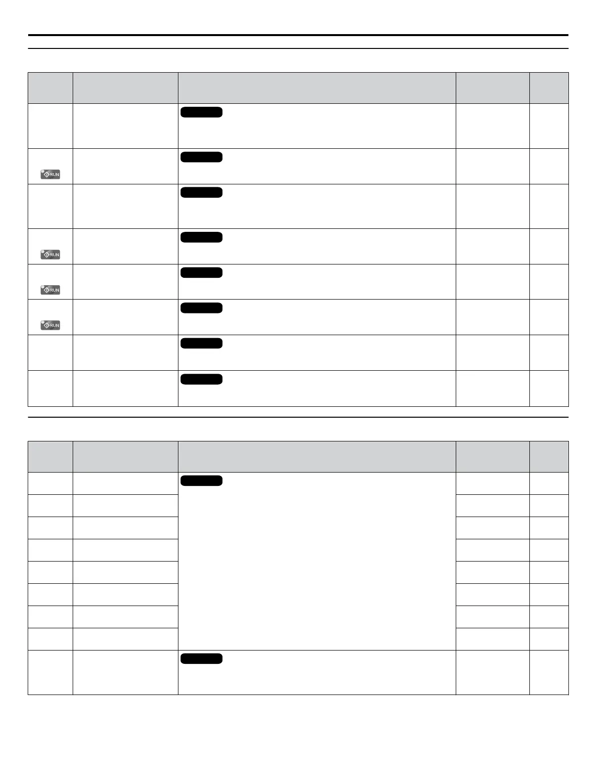
F4: Analog Monitor Card (AO-A3)
No.
(Addr.
Hex)
Name Description Values Page
F4-01
(391)
Terminal V1 Monitor
Selection
All Modes
Sets the monitor signal for output from terminal V1. Set this parameter to the
last three digits of the desired Uo-oo monitor. Some U parameters are
available only in certain control modes.
Default: 102
Range: 000 to 999
200
F4-02
(392)
Terminal V1 Monitor Gain
All Modes
Sets the gain for voltage output via terminal V1.
Default: 100.0%
Min.: -999.9
Max.: 999.9
200
F4-03
(393)
Terminal V2 Monitor
Selection
All Modes
Sets the monitor signal for output from terminal V2. Set this parameter to the
last three digits of the desired Uo-oo monitor. Some U parameters are
available only in certain control modes.
Default: 103
Range: 000 to 999
200
F4-04
(394)
Terminal V2 Monitor Gain
All Modes
Sets the gain for voltage output via terminal V2.
Default: 50.0%
Min.: -999.9
Max.: 999.9
200
F4-05
(395)
Terminal V1 Monitor Bias
All Modes
Sets the amount of bias added to the voltage output via terminal V1.
Default: 0.0%
Min.: -999.9
Max.: 999.9
200
F4-06
(396)
Terminal V2 Monitor Bias
All Modes
Sets the amount of bias added to the voltage output via terminal V2.
Default: 0.0%
Min.: -999.9
Max.: 999.9
200
F4-07
(397)
Terminal V1 Signal Level
All Modes
0: 0 to 10 V
1: -10 to 10 V
Default: 0
Range: 0, 1
201
F4-08
(398)
Terminal V2 Signal Level
All Modes
0: 0 to 10 V
1: -10 to 10 V
Default: 0
Range: 0, 1
201
u
F5: Digital Output Card (DO-A3)
No.
(Addr.
Hex)
Name Description Values Page
F5-01
(399)
Terminal P1-PC Output
Selection
All Modes
Sets the function for contact output terminals M1-M2, M3-M4, and
photocoupler output terminals P1 through P6.
Default: 2
Range: 0 to 192
201
F5-02
(39A)
Terminal P2-PC Output
Selection
Default: 4
Range: 0 to 192
201
F5-03
(39B)
Terminal P3-PC Output
Selection
Default: 6
Range: 0 to 192
201
F5-04
(39C)
Terminal P4-PC Output
Selection
Default: 37
Range: 0 to 192
201
F5-05
(39D)
Terminal P5-PC Output
Selection
Default: F
Range: 0 to 192
201
F5-06
(39E)
Terminal P6-PC Output
Selection
Default: F
Range: 0 to 192
201
F5-07
(39F)
Terminal M1-M2 Output
Selection
Default: 0
Range: 0 to 192
201
F5-08
(3A0)
Terminal M3-M4 Output
Selection
Default: 1
Range: 0 to 192
201
F5-09
(3A1)
DO-A3 Output Mode
Selection
All Modes
0: Output terminals are each assigned separate output functions.
1: Binary code output.
2: Use output terminal functions selected by parameters F5-01 through F5-08.
Default: 0
Range: 0 to 2
201
B.8 F: Options
410
YASKAWA ELECTRIC SIEP C710616 31B YASKAWA AC Drive – A1000 Technical Manual

 Loading...


