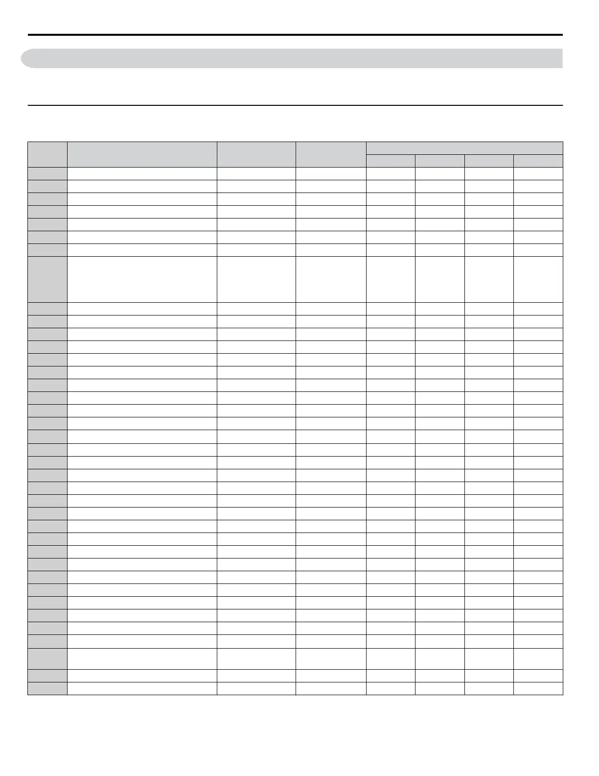
B.16 Control Mode Dependent Parameter Default Values
The tables below list parameters that depend on the control mode selection (A1-02 for motor 1, E3-01 for motor 2). Changing
the control mode initializes these parameters to the values shown here.
u
A1-02 (Motor 1 Control Mode) Dependent Parameters
Table B.2 A1-02 (Motor 1 Control Mode) Dependent Parameters and Default Values
No. Name Setting Range Resolution
Control Modes (A1-02)
V/f (0) V/f w/PG (1) OLV (2) CLV (3)
b2-01 DC Injection Braking Start Frequency 0.0 to 10.0 0.1 Hz 0.5 0.5 0.5 0.5
b2-04 DC Injection Braking Time at Stop 0.00 to 10.00 0.01 s 0.50 0.50 0.50 0.50
b3-01 Speed Search Selection at Start 0 to 1 – 0 1 0 1
b3-02 Speed Search Deactivation Current 0 to 200 1% 120 – 100 –
b3-14 Bi-Directional Speed Search Selection 0 to 1 1 1 0 1 1
b8-01 Energy Saving Control Selection 0 to 1 – 0 0 0 0
b8-02 Energy Saving Gain 0.0 to 10.0 0.1 – – 0.7 1.0
b8-03 Energy Saving Control Filter Time Constant 0.00 to 10.00 0.01 s – –
0.50
2.00 (Motor
Capacity: 55
kW and
above)
0.01
0.05 (Motor
Capacity: 55
kW and
above)
C2-01 S-Curve Time at Acceleration Start 0.00 to 10.00 0.01 s 0.20 0.20 0.20 0.20
C3-01 Slip Compensation Gain 0.0 to 2.5 0.1 0.0 – 1.0 1.0
C3-02 Slip Compensation Primary Delay Time 0 to 10000 1 ms 2000 – 200 –
C4-01 Torque Compensation Gain 0.00 to 2.50 0.01 1.00 1.00 1.00 –
C4-02 Torque Compensation Primary Delay Time 0 to 10000 1 ms 200 200 20 –
C5-01 ASR Proportional Gain 1 0.00 to 300.00 0.01 – 0.20 – 20.00
C5-02 ASR Integral Time 1 0.000 to 10.000 0.001 s – 0.200 – 0.500
C5-03 ASR Proportional Gain 2 0.00 to 300.00 0.01 – 0.02 – 20.00
C5-04 ASR Integral Time 2 0.000 to 10.000 0.001 s – 0.050 – 0.500
C5-06 ASR Primary Delay Time Constant 0.000 to 0.500 0.001 s – – – 0.004
C6-02 Carrier Frequency Selection 1 to F –
7
<1>
7
<1>
7
<1>
7
<1>
E1-04 Maximum Output Frequency 40.0 to 400.0 0.1 Hz 60.0 60.0 60.0 60.0
E1-05 Maximum Voltage 0.0 to 733.1 0.1 V 575 575 575 575
E1-06 Base Frequency 0.0 to 400.0 0.1 Hz 60.0 60.0 60.0 60.0
E1-07 Middle Output Frequency 0.0 to 400.0 0.1 Hz 3.0 3.0 3.0 3.0
E1-08 Middle Output Frequency Voltage 0.0 to 733.1 0.1 V 15.0 15.0 15.0 15.0
E1-09 Minimum Output Frequency 0.0 to 400.0 0.1 Hz 1.5 1.5 0.5 0.0
E1-10 Minimum Output Frequency Voltage 0.0 to 733.1 0.1 V 9.0 9.0 2.0 0.0
F1-01 PG 1 Pulses Per Revolution 0 to 60000 1 ppr 600 600 600 600
F1-05 PG 1 Rotation Selection 0 to 1 – 0 0 0 0
F1-09 Overspeed Detection Delay Time 0.0 to 2.0 0.1 s – 1.0 – 0.0
L1-01 Motor Overload Protection Selection 0 to 4 – 1 1 1 1
L3-20 DC Bus Voltage Adjustment Gain 0.00 to 5.00 0.01 1.00 1.00 0.30 0.30
L3-21 Accel/Decel Rate Calculation Gain 0.00 to 10.00 0.01 1.00 1.00 1.00 1.00
L4-02 Speed Agreement Detection Width 0.0 to 20.0 0.1 Hz 2.0 2.0 2.0 2.0
L4-04 Speed Agreement Detection Width (+/-) 0.0 to 20.0 0.1 Hz 2.0 2.0 2.0 2.0
L8-38 Carrier Frequency Reduction Selection 0 to 2 1
<1> <1> <1> <1>
L8-40
Carrier Frequency Reduction Off Delay
Time
0.00 to 2.00 0.01 s 0.50 0.50 0.50 0.50
o1-03 Digital Operator Display Selection 0 to 3 1 0 0 0 0
o1-04 V/f Pattern Display Unit 0 to 1 1 — — — 0
<1> Default setting is dependent on parameters C6-01, Drive Duty Selection, and o2-04, Drive Model Selection.
B.16 Control Mode Dependent Parameter Default Values
456
YASKAWA ELECTRIC SIEP C710616 31B YASKAWA AC Drive – A1000 Technical Manual

 Loading...


