No.
(Addr.
Hex)
Name Description Values Page
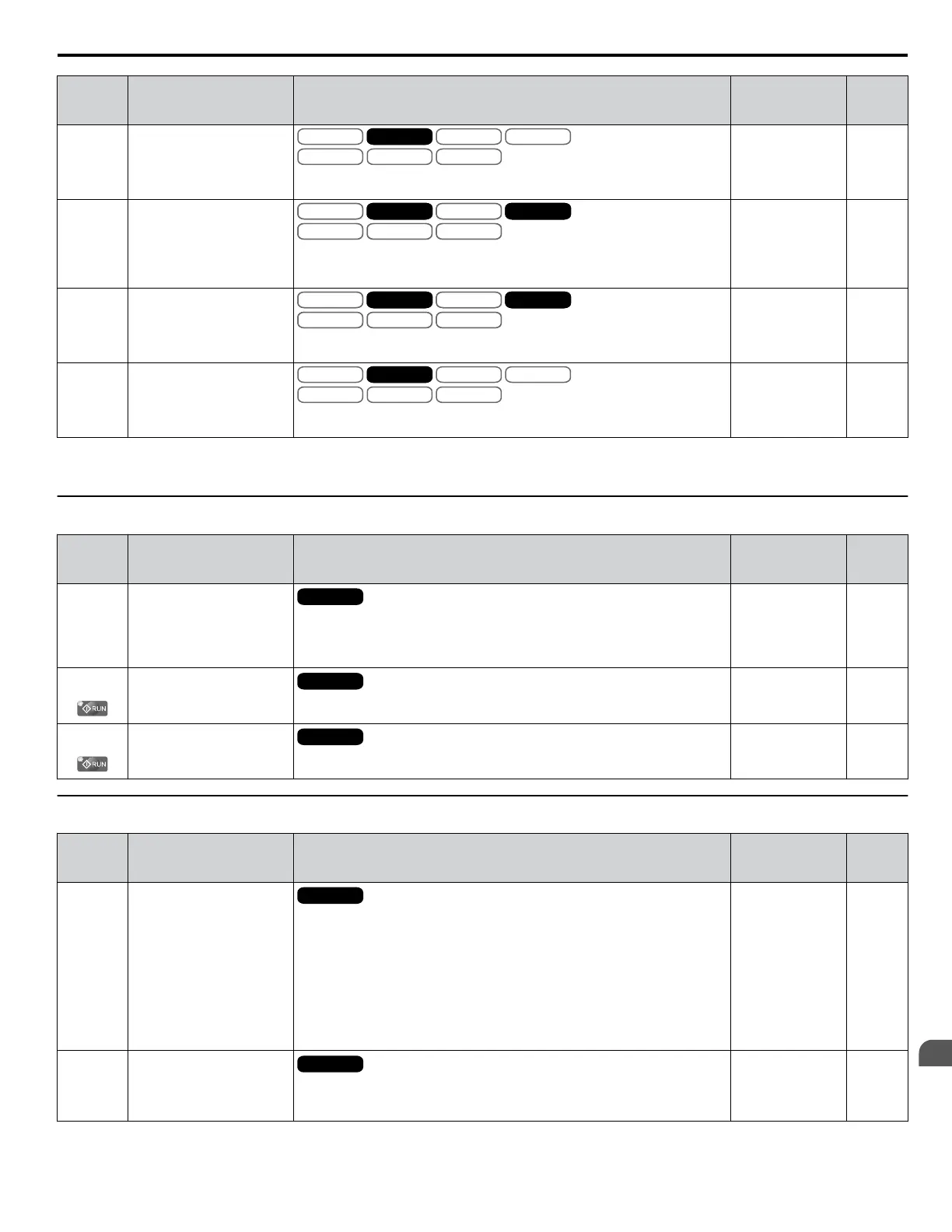
F1-34
(3B3)
PG 2 Gear Teeth 2
V/f
OLV/PM
V/f w PG
AOLV/PM
OLV
CLV/PM
CLVV/f w PG
Sets the gear ratio between the motor shaft and the encoder (PG). A gear ratio
of 1 will be used if F1-33 or F1-34 are set to 0.
Default: 0
Min.: 0
Max.: 1000
197
F1-35
(3BE)
PG 2 Division Rate for Pulse
Monitor
V/f
OLV/PM
V/f w PG
AOLV/PM
OLV
CLV/PM
CLVV/f w PG CLVV/f
OLV/PM
V/f w PG
AOLV/PM
OLV
CLV/PM
CLVV/f w PG CLV
Sets the division ratio for the pulse monitor used of the PG option card 2
installed to port CN5-B.
By setting “xyz”, the division ratio becomes = [(1 + x) / yz].
Default: 1
Min.: 1
Max.: 132
197
F1-36
(3B5)
PG Option Card Disconnect
Detection 2
V/f
OLV/PM
V/f w PG
AOLV/PM
OLV
CLV/PM
CLVV/f w PG CLVV/f
OLV/PM
V/f w PG
AOLV/PM
OLV
CLV/PM
CLVV/f w PG CLV
0: Disabled
1: Enabled
Default: 1
Range: 0, 1
198
F1-37
(3BD)
PG 2 Signal Selection
V/f
OLV/PM
V/f w PG
AOLV/PM
OLV
CLV/PM
CLVV/f w PG
0: A pulse detection
1: AB pulse detection
Default: 0
Range: 0, 1
198
<1> Default setting is determined by parameter A1-02, Control Mode Setting.
u
F2: Analog Input Card (AI-A3)
No.
(Addr.
Hex)
Name Description Values Page
F2-01
(38F)
Analog Input Option Card
Operation Selection
All Modes
0: Option card input terminals V1, V2, and V3 replace drive input terminals
A1, A2, and A3.
1: Input signals to terminals V1, V2, and V3 are added together to create the
frequency reference.
Default: 0
Range: 0, 1
199
F2-02
(368)
Analog Input Option Card
Gain
All Modes
Sets the gain for the input signal to the analog card.
Default: 100.0%
Min.: -999.9
Max.: 999.9
199
F2-03
(369)
Analog Input Option Card
Bias
All Modes
Sets the bias for the input signal to the analog card.
Default: 0.0%
Min.: -999.9
Max.: 999.9
199
u
F3: Digital Input Card (DI-A3)
No.
(Addr.
Hex)
Name Description Values Page
F3-01
(390)
Digital Input Option Card
Input Selection
All Modes
0: BCD, 1% units
1: BCD, 0.1% units
2: BCD, 0.01% units
3: BCD, 1 Hz units
4: BCD, 0.1 Hz units
5: BCD, 0.01 Hz units
6: BCD customized setting (5 digit), 0.02 Hz units
7: Binary input
When the digital operator units are set to be displayed in Hertz or user-set units
(o1-03 = 2 or 3), the units for F3-01 are determined by parameter o1-03.
Default: 0
Range: 0 to 7
199
F3-03
(3B9)
Digital Input Option DI-A3
Data Length Selection
All Modes
0: 8 bit
1: 12 bit
2: 16 bit
Default: 2
Range: 0 to 2
200
B.8 F: Options
YASKAWA ELECTRIC SIEP C710616 31B YASKAWA AC Drive – A1000 Technical Manual
409
B
Parameter List

 Loading...


