8.4 Option Card Installation
This section provides instructions on installing the option cards listed in Table 8.1.
u
Installing Option Cards
Table 8.2 below lists the number of option cards that can be connected to the drive and the drive ports for connecting those
option cards.
Table 8.2 Option Card Installation
Option Card Port/Connector Number of Cards Possible
SI-C3, SI-N3, SI-P3, SI-S3, SI-T3, AI-A3, DI-A3
<1>
CN5-A 1
PG-B3, PG-X3 CN5-B, C
2
<2>
DO-A3, AO-A3 CN5-A, B, C 1
<1> Option cards AI-A3 and DI-A3 cannot set the frequency reference when installed to ports CN5-B or CN5-C. It is still possible, however, to view
the input status using U1-21, U1-22, U1-23 (for AI-A3), and U1-17 (for DI-A3).
<2> Use port CN5-C when connecting one PG option card. Use ports CN5-B and CN5-C when connecting two PG option cards.
u
Installation Procedure
WARNING! Electrical Shock Hazard. Do not allow unqualified personnel to perform work on the drive. Failure to comply could result in death
or serious injury. Maintenance, inspection, and replacement of parts must be performed only by authorized personnel familiar with
installation, adjustment and maintenance of AC drives and Option Cards.
NOTICE: Damage to Equipment. Observe proper electrostatic discharge procedures (ESD) when handling the option card, drive, and circuit
boards. Failure to comply may result in ESD damage to circuitry.
NOTICE: Damage to Equipment. Tighten all terminal screws to the specified tightening torque. Failure to comply may cause the application
to operate incorrectly or damage the drive.
Use the procedure described below when installing option cards to the drive.
1.
Shut off power to the drive, wait the appropriate amount of time for voltage to dissipate, then remove the operator and
front cover. Refer to Digital Operator and Front Cover on page 56.
2.
Insert the CN5 connector on the option card into the matching CN5 connector on the drive, then fasten it into place
using one of the screws included with the option card.
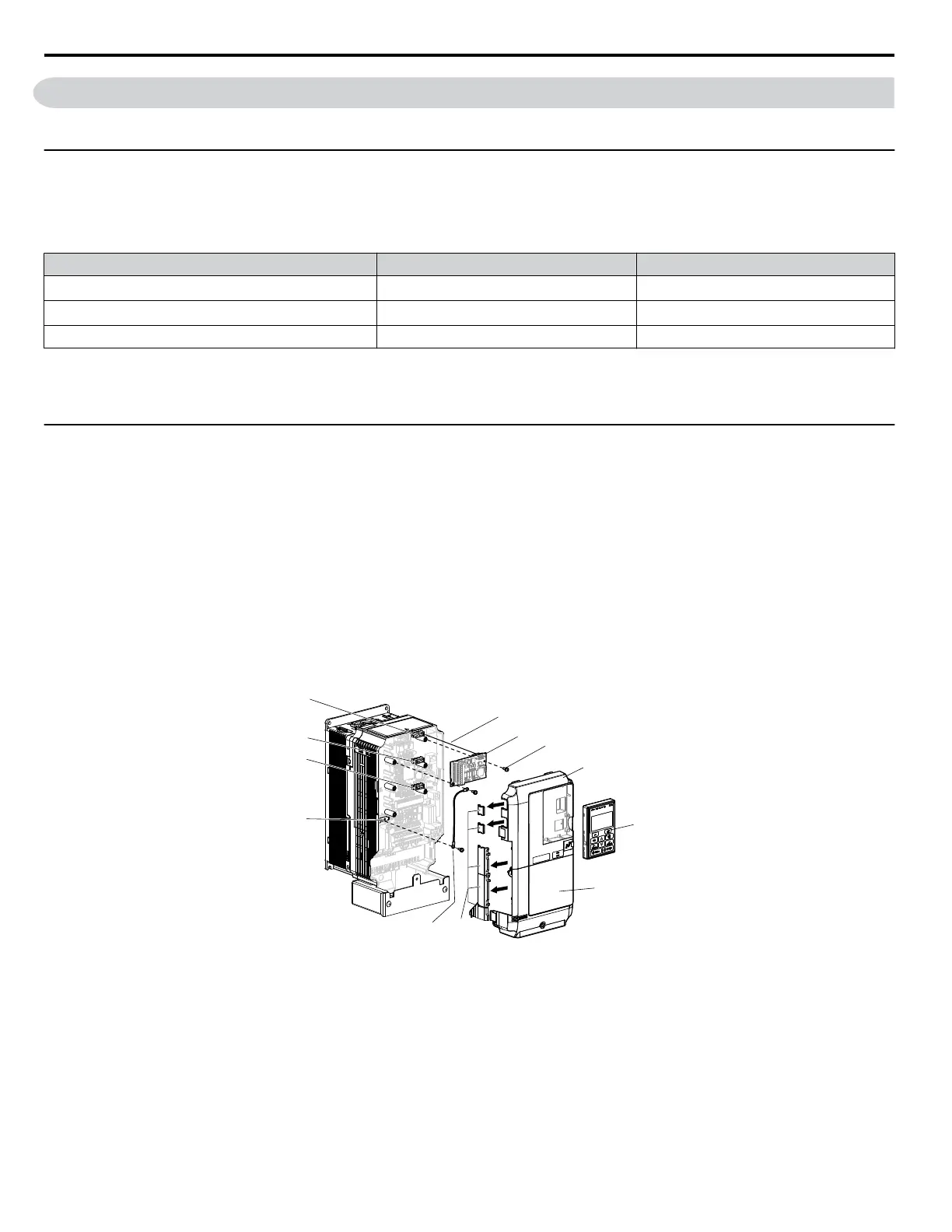
A
B
C
D
E
F
G
J
K
L
I
H
A – Connector CN5-C
B – Connector CN5-B
C – Connector CN5-A
D – Drive grounding terminal (FE)
E – Insert connector CN5 here
F – Option card
G – Mounting screw
H – Lead line
I – Use wire cutters to create an
opening for cable lines
J – Front cover
K – Digital operator
L – Terminal cover
Figure 8.2 Installing an Option Card
3.
Connect one of the lead lines to the ground terminal using one of the screws.
8.4 Option Card Installation
364
YASKAWA ELECTRIC SIEP C710616 31B YASKAWA AC Drive – A1000 Technical Manual

 Loading...


