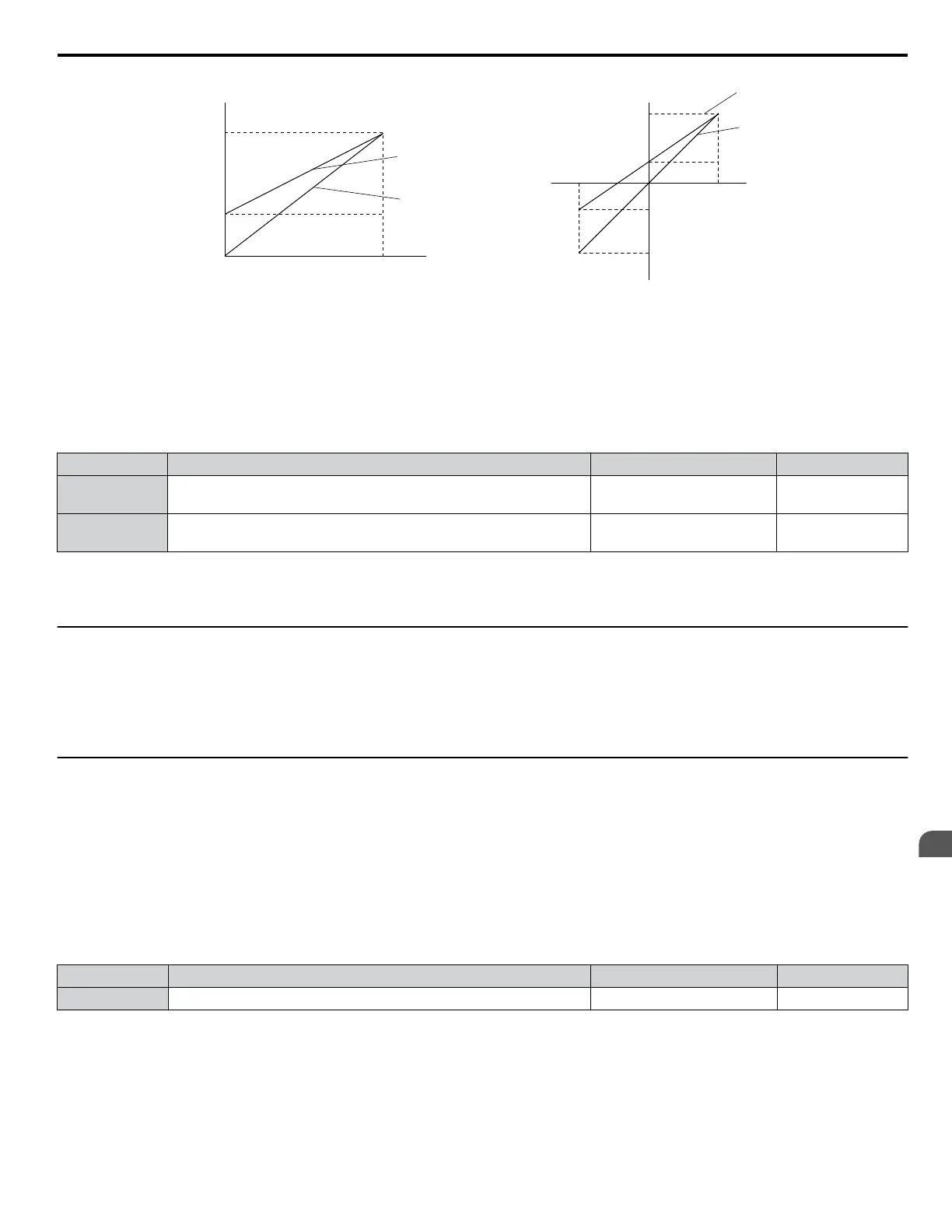
Gain = 100%
Bias = 30%
Gain = 100%
Bias = 0%
Gain 100%
Bias 30%
Gain 100%
Bias 0%
Monitor Value
Monitor Value
0 V
3 V
10 V
100%0%
Output Voltage
Output Voltage
H4-07, 08 = 0 H4-07, 08 = 1
10V
-10 V
100%
3 V
-4 V
-100%
Figure 5.84 Analog Output Gain and Bias Setting Example 3
n
H4-07, H4-08: Multi-Function Analog Output Terminal FM, AM Signal Level Selection
Sets the voltage output level of U parameter (monitor parameter) data to terminal FM and terminal AM using parameters
H4-07 and H4-08.
Set jumper S5 on the terminal board accordingly when changing these parameters. Refer to Terminal AM/FM Signal
Selection on page 71 for details on setting S5.
No. Name Setting Range Default
H4-07
Multi-Function Analog Output Terminal FM
Signal Level Selection
0 to 2 0
H4-08
Multi-Function Analog Output Terminal AM
Signal Level Selection
0 to 2 0
Setting 0: 0 to 10 V
Setting 1: -10 V to 10 V
Setting 2: 4 to 20 mA
u
H5: MEMOBUS/Modbus Serial Communication
Serial communication is possible in the drive using the built-in RS-422/485 port (terminals R+, R-, S+, S-) and programmable
logic controllers (PLCs) or similar devices running the MEMOBUS/Modbus protocol.
The H5-oo parameters set the drive for MEMOBUS/Modbus Communications. Refer to MEMOBUS/Modbus Serial
Communication on page 468 for detailed descriptions of the H5-oo parameters.
u
H6: Pulse Train Input/Output
A one-track pulse train signal with a maximum frequency of 32 kHz can be input to the drive at terminal RP. This pulse train
signal can be used as the frequency reference, for PID functions, or as the speed feedback signal in V/f Control.
The pulse output monitor terminal MP can output drive monitor values as a pulse train signal with a maximum frequency of
32 kHz in sinking or sourcing mode. Refer to Using the Pulse Train Output on page 69 for details.
Use parameters H6-oo to set the scale and other aspects of the pulse input terminal RP and pulse output terminal MP.
n
H6-01: Pulse Train Input Terminal RP Function Selection
Selects the function of pulse train input terminal RP.
No. Name Setting Range Default
H6-01 Pulse Train Input Terminal RP Function Selection 0 to 3 0
Setting 0: Frequency reference
If the pulse input is set for this function and the frequency reference source is set to pulse input (b1-01, b1-15 = 4), the drive
reads the frequency value from terminal RP.
Setting 1: PID feedback value
Using this setting, the feedback value for PID control can be supplied as a pulse signal at terminal RP. Refer to b5: PID
Control on page 141 for details on PID control.
5.7 H: Terminal Functions
YASKAWA ELECTRIC SIEP C710616 31B YASKAWA AC Drive – A1000 Technical Manual
235
5
Parameter Details

 Loading...


