n
b1-16: Run Command Selection 2
Refer to b1-02: Run Command Selection 1 on page 127.
No. Parameter Name Setting Range Default
b1-16 Run Command Selection 2 0 to 3 0
n
b1-17: Run Command at Power Up
Determines whether an external Run command that is active during power up will start the drive.
No. Parameter Name Setting Range Default
b1-17 Run Command at Power Up 0, 1 0
Setting 0: Run command at power up is not issued
Cycle the Run command to start the drive.
Note: For safety reasons, the drive is initially programmed not to accept a Run command at power up (b1-17 = 0). If a Run command is issued at
power up, the RUN indicator LED will flash quickly.
Setting 1: Run command and power up is issued
If an external Run command is active when the drive is powered up, the drive will begin operating the motor once the internal
start up process is complete.
WARNING! Sudden Movement Hazard. If b1-17 is set to 1 and an external Run command is active during power up, the motor will begin
rotating as soon as the power is switched on. Proper precautions must be taken to ensure that the area around the motor is safe prior to
powering up the drive. Failure to comply may cause serious injury.
u
b2: DC Injection Braking and Short Circuit Braking
These parameters determine operation of the DC Injection Braking, Zero Speed Control, and Short Circuit Braking features.
n
b2-01: DC Injection Braking Start Frequency
Active when “Ramp to Stop” is selected as the stopping method (b1-03 = 0).
No. Name Setting Range Default
b2-01 DC Injection Braking Start Frequency 0.0 to 10.0 Hz
Determined by
A1-02
The function triggered by parameter b2-01 depends on the control mode that has been selected.
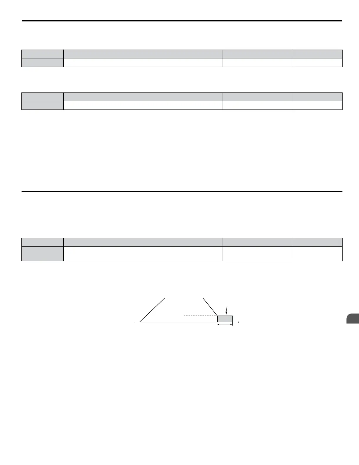
V/f, V/f w/PG, and OLV (A1-02 = 0, 1, 2)
For these control modes, parameter b2-01 sets the starting frequency for DC Injection Braking at Stop. When the output
frequency falls below the setting of b2-01, DC Injection Braking is enabled for the time set in parameter b2-04.
Output
frequency
Time
b2-04
DC Injection
Braking
E1-09 Min. Frequency
b2-01 Zero Speed Level
Figure 5.12 DC Injection Braking at Stop for V/f, V/f w/PG and OLV
Note: If b2-01 is set to a smaller value than parameter E1-09 (minimum frequency), then DC Injection Braking will begin as soon as the frequency
falls to the value set to E1-09.
OLV/PM and AOLV/PM (A1-02 = 5, 6)
Note:
PM motor control modes are not available on 600 V class drives, CIMR-Ao5oooooooo.
For these control modes, parameter b2-01 sets the starting frequency for Short-Circuit Braking at stop. When the output
frequency falls below the setting of b2-01, Short-Circuit Braking is enabled for the time set in parameter b2-13. If DC Injection
Braking time is enabled at stop, then DC Injection Braking is performed for the time set in b2-04 after Short-Circuit Braking
is complete.
5.2 b: Application
YASKAWA ELECTRIC SIEP C710616 31B YASKAWA AC Drive – A1000 Technical Manual
133
5
Parameter Details

 Loading...


