Setting 90 to 97: DriveWorksEZ Digital Input 1 to 8
These settings are for digital inputs functions used in DriveWorksEZ. Changing these settings is not typically required.
Setting 9F: DriveWorksEZ Disable
This function is used to enable or disable a DriveWorksEZ program in the drive. An input programmed for this function is
effective only if A1-07 = 2.
Status Description
Open DriveWorksEZ enabled
Closed DriveWorksEZ disabled
u
H2: Multi-Function Digital Outputs
n
H2-01 to H2-03: Terminal M1-M2, M3-M4, and M5-M6 Function Selection
The drive has three multi-function output terminals. Table 5.34 lists the functions available for theses terminals using H2-01,
H2-02, and H2-03.
No. Parameter Name Setting Range Default
H2-01 Terminal M1-M2 Function Selection (relay) 0 to 192 0: During run
H2-02 Terminal M3-M4 Function Selection (open-collector) 0 to 192 1: Zero Speed
H2-03 Terminal M5-M6 Function Selection (open-collector) 0 to 192 2: Speed agree 1
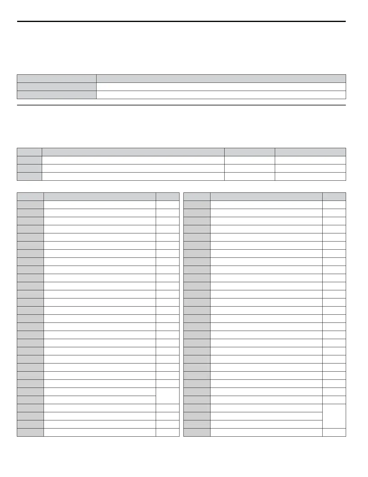
Table 5.34 Multi-Function Digital Output Terminal Settings
Setting Function Page
0 During Run 219
1 Zero Speed 219
2 Speed Agree 1 219
3 User-Set Speed Agree 1 220
4 Frequency Detection 1 220
5 Frequency Detection 2 221
6 Drive Ready 221
7 DC Bus Undervoltage 221
8 During Baseblock (N.O.) 222
9 Frequency Reference Source 222
A Run Command Source 222
B Torque Detection 1 (N.O.) 222
C Frequency Reference Loss 222
D Braking Resistor Fault 222
E Fault 222
F Through Mode 222
10 Minor Fault 222
11 Fault Reset Command Active 222
12 Timer Output 223
13 Speed Agree 2 223
14 User-Set Speed Agree 2 223
15 Frequency Detection 3 223
16 Frequency Detection 4 224
17 Torque Detection 1 (N.C.)
222
18 Torque Detection 2 (N.O.)
19 Torque Detection 2 (N.C.) 222
1A During Reverse 224
1B During Baseblock (N.C.) 225
1C Motor 2 Selection 225
Setting Function Page
1D During regeneration 225
1E Restart Enabled 225
1F Motor Overload Alarm (oL1) 225
20 Drive Overheat Pre-Alarm (oH) 225
22 Mechanical Weakening Detection 225
2F Maintenance Period 225
30 During Torque Limit 225
31 During Speed Limit 226
32 During Speed Limit in Torque Control 226
33 Zero Servo Complete 226
37 During Frequency Output 226
38 Drive Enabled 226
39 Watt Hour Pulse Output 226
3C LOCAL/REMOTE Status 226
3D During Speed Search 227
3E PID Feedback Low 227
3F PID Feedback High 227
4A During KEB Operation 227
4B During Short Circuit Braking 227
4C During Fast Stop 227
4D oH Pre-Alarm Time Limit 227
4E Braking Transistor Fault (rr) 227
4F Braking Resistor Overheat (rH) 227
60 Internal Cooling Fan Alarm 227
61 Rotor Position Detection Completed 227
90 DriveWorksEZ Digital Output 1
22791 DriveWorksEZ Digital Output 2
92 DriveWorksEZ Digital Output 3
100 to 192 Functions 0 to 92 with Inverse Output 227
5.7 H: Terminal Functions
218
YASKAWA ELECTRIC SIEP C710616 31B YASKAWA AC Drive – A1000 Technical Manual

 Loading...


