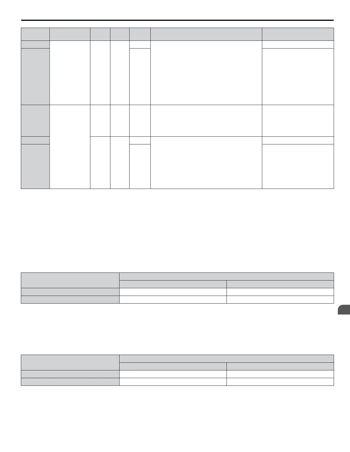
Condition
Freq. Ref.
Source
d4-03 d4-05 d4-01 Operation Frequency Saved
6
Other (analog
comm., etc.)
0 0
0 • Accelerates (increases the bias) while the Up 2
terminal is closed.
• Decelerates (decreases the bias) while Down 2 is
closed.
• Holds output frequency (holds the bias) when
neither Up/Down 2 inputs are active or both inputs
are active.
• If the frequency reference changes for more than
the time set to d4-07 during accel/decel, bias value
is held until the output frequency meets the
reference (speed agree).
Not saved
7 1
If the bias is constant for 5 s, it is
saved to parameter d4-06. The
frequency reference cannot be
overwritten, so only the bias is
saved.
8
Other (analog
comm, etc.)
0 1 --
• Accelerates (increases the bias) while the Up 2
terminal is closed.
• Decelerates (decreases the bias) while Down 2 is
closed.
• Otherwise operates at the frequency reference
Not saved
9
Value
other
than 0
--
0 • When Up 2 is enabled, drive accelerates to the
frequency reference plus d4-03 (increases the bias
for d4-03).
• When Down 2 is enabled, drive decelerates to the
frequency reference minus d4-03 (decreases the
bias for d4-03).
• If the frequency reference changes for more then
d4-07 during accel/decel, bias value is held until the
output frequency meets the reference (speed agree).
Not saved
10 1
If the bias is constant for 5 s, it is
saved to parameter d4-06. The
frequency reference cannot be
overwritten, so only the bias is
saved.
Setting 77: ASR Gain Switch
Switches the ASR gain between the values set to C5-01 and C5-03. The gain set to C5-03 is enabled when the terminal is
closed, and C5-01 is enabled when the terminal reopens. Refer to C5-01, C5-03/C5-02, C5-04: ASR Proportional Gain 1, 2/
ASR Integral Time 1, 2 on page 163 for a more detailed description.
Setting 78: External Torque Reference Polarity Inversion
Reverses the direction of the torque reference when the terminal closes. Refer to d5: Torque Control on page 178 and Setting
the Torque Reference, Speed Limit, and Torque Compensation Values for details.
Setting 7A, 7B: KEB Ride-Thru 2 (N.C., N.O.)
An input terminal set to 7A or 7B can trigger Single Drive KEB Ride-Thru during deceleration. L2-29 is disregarded if this
is enabled. Refer to KEB Ride-Thru Function on page 243 for details.
Digital Input Function
Drive Operation
Input Open Input Closed
Setting 7A (N.C.) Single Drive KEB Ride-Thru 2 Normal operation
Setting 7B (N.O.) Normal operation Single Drive KEB Ride-Thru 2
Note: Simultaneously assigning KEB Ride-Thru 1 and KEB Ride-Thru 2 to the input terminals will trigger an oPE03 error.
Setting 7C, 7D: Short Circuit Braking (N.O., N.C.) (OLV/PM, AOLV/PM)
Note:
PM motor control modes are not available on 600 V class drives, CIMR-Ao5oooooooo.
Activates Short Circuit Braking in OLV control modes for PM motors. By linking all three phases of a PM motor, Short Circuit
Braking creates a braking torque to stop a rotating motor or prevent a motor from coasting due to external forces (such as the
windmill effect in fan applications). Parameter b2-18 limits the current during Short Circuit Braking.
DIgital Input Function
Drive Operation
Input Open Input Closed
Setting 7C (N.O.) Normal operation Short Circuit Braking
Setting 7D (N.C.) Short-Circuit Braking Normal operation
Setting 7E: Forward/Reverse Detection (for V/f Control with Simple PG Feedback)
Determines the motor rotation direction for V/f Control with Simple PG feedback (A1-02 = 0 and H6-01 = 3). If the input is
open, the speed feedback signal is considered to be forward. If the input is closed, it is considered to be reverse. Refer to H6:
Pulse Train Input/Output on page 235.
5.7 H: Terminal Functions
YASKAWA ELECTRIC SIEP C710616 31B YASKAWA AC Drive – A1000 Technical Manual
217
5
Parameter Details

 Loading...


