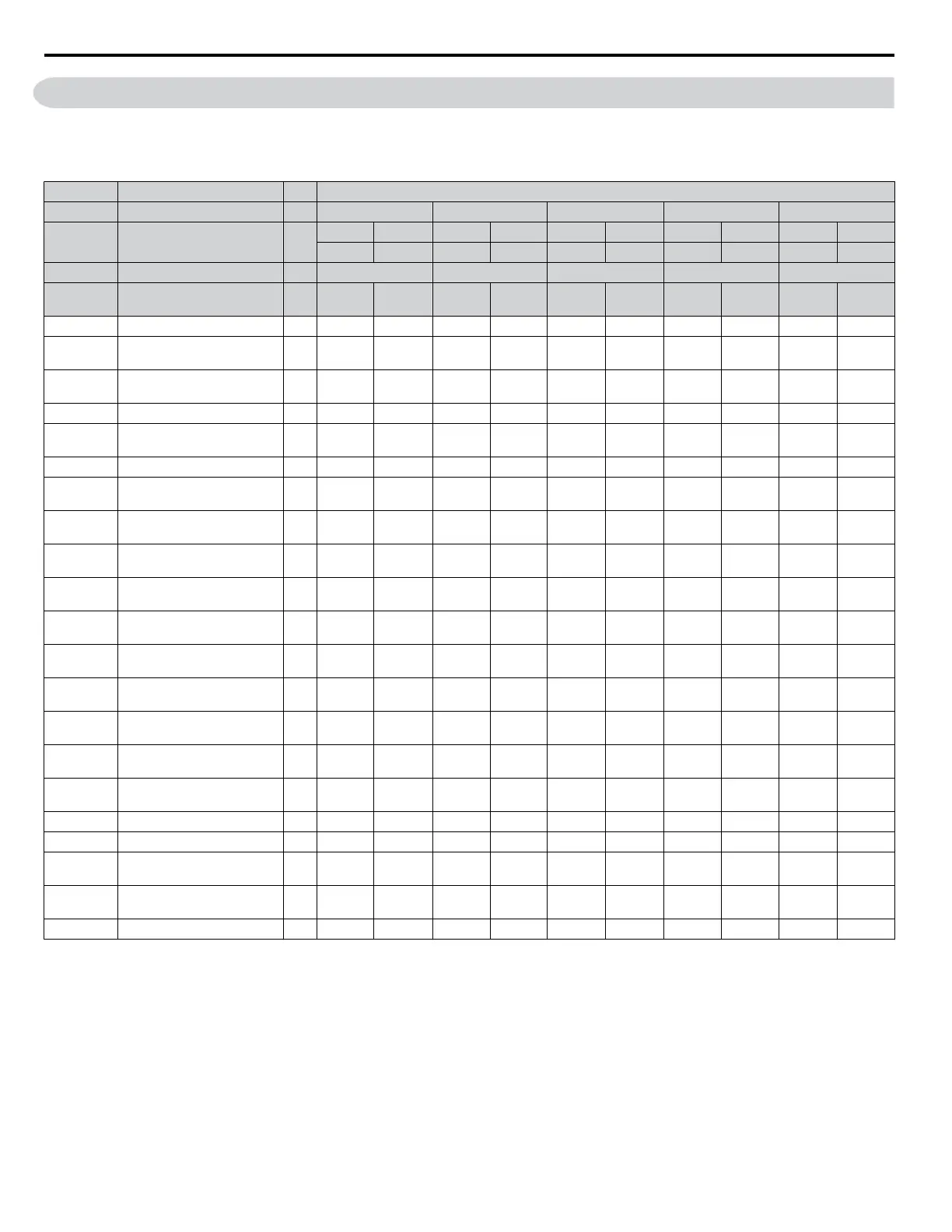
B.18 Defaults by Drive Model (o2-04) and ND/HD (C6-01)
The following tables show parameters and default settings that change with the drive model selection (o2-04) and drive duty
selection (C6-01). Parameter numbers shown in parenthesis are valid for motor 2.
Table B.7 600 V Class Drives Default Settings by Drive Model and ND/HD Setting
No. Name Unit Default Settings
–
Model CIMR-Ao
– 5A0003 5A0004 5A0006 5A0009 5A0011
C6-01 Drive Duty Selection –
HD ND HD ND HD ND HD ND HD ND
0 1 0 1 0 1 0 1 0 1
o2-04 Drive Model Selection Hex. C3H C4H C5H C7H C9H
E2-11
(E4-11)
Motor Rated Power kW 0.75 1.5 1.5 2.2 2.2 3.7 3.7 5.5 5.5 7.5
b3-04 V/f Gain during Speed Search % 100 100 100 100 100 100 100 100 100 100
b3-06
Output Current 1 during Speed
Search
– 0.5 0.5 0.5 0.5 0.5 0.5 0.5 0.5 0.5 0.5
b8-03
Energy Saving Control Filter
Time Constant
s 0.50 0.50 0.50 0.50 0.50 0.50 0.50 0.50 0.50 0.50
b8-04 Energy Saving Coefficient Value – 541.9 494.4 494.4 415.3 415.3 320.2 320.2 239.95 239.95 199.86
C5-17
(C5-37)
Motor Inertia
kgm
2
0.0028 0.0068 0.0068 0.0088 0.0088 0.0158 0.0158 0.0255 0.026 0.037
C6-02 Carrier Frequency Selection – 1 7 1 7 1 7 1 7 1 7
E2-01
(E4-01)
Motor Rated Current A 1.7 2.7 2.7 3.9 3.9 6.1 6.1 9 9 11
E2-02
(E4-02)
Motor Rated Slip Hz 2.5 2.5 2.5 3.0 3.0 2.7 2.7 1.5 1.5 1.3
E2-03
(E4-03)
Motor No-Load Current A 0.8 0.8 0.8 1.2 1.2 1.8 1.8 2.7 2.7 3.3
E2-05
(E4-05)
Motor Line-to-Line Resistance Ω 21.9 13.72 13.72 8.825 8.825 4.936 4.936 2.601 2.601 1.446
E2-06
(E4-06)
Motor Leakage Inductance % 18.3 18.3 18.3 18.7 18.7 19.3 19.3 18.2 18.2 15.5
E2-10
(E4-10)
Motor Iron Loss for Torque
Compensation
W 53 53 53 77 77 130 130 193 193 263
L2-02
Momentary Power Loss Ride-
Thru Time
s 0.2 0.2 0.3 0.3 0.5 0.5 0.5 0.5 0.8 0.8
L2-03
Momentary Power Loss
Minimum Baseblock Time
s 0.5 0.5 0.5 0.5 0.5 0.8 0.8 0.8 0.8 1
L2-04
Momentary Power Loss Voltage
Recovery Time
s 0.5 0.5 0.5 0.5 0.5 0.6 0.6 0.7 0.7 0.8
L3-24
Motor Acceleration Time for
Inertia Calculations
s 0.142 0.166 0.166 0.145 0.145 0.154 0.154 0.168 0.168 0.175
L8-02 Overheat Alarm Level °C 110 110 110 110 110 110 110 110 115 115
L8-35 Installation Method Selection – 2 2 2 2 2 2 2 2 2 2
L8-38
Carrier Frequency Reduction
Selection
– 2 2 2 2 2 2 2 2 2 2
n1-03
Hunting Prevention Time
Constant
ms 10 10 10 10 10 10 10 10 10 10
n5-02 Motor Acceleration Time s 0.142 0.166 0.166 0.145 0.145 0.154 0.154 0.168 0.168 0.175
B.18 Defaults by Drive Model (o2-04) and ND/HD (C6-01)
460
YASKAWA ELECTRIC SIEP C710616 31B YASKAWA AC Drive – A1000 Technical Manual

 Loading...


