u
d5: Torque Control
Torque Control defines a setpoint for the motor torque and is available for CLV and CLV/PM (A1-02 = 3, 7).
Note:
PM motor control modes are not available on 600 V class drives, CIMR-Ao5oooooooo.
n
Torque Control Operation
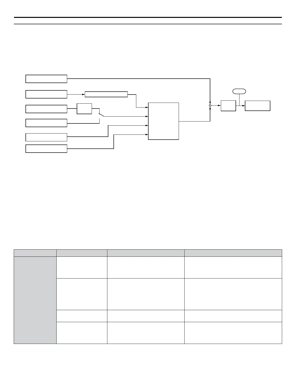
Torque control can be enabled either by setting parameter d5-01 to 1 or by setting digital input (H1-oo = 71). Figure 5.49
illustrates the working principle.
Torque Compensation
External Torque Reference
External Speed Limit
Speed Limit set in d5-04
Speed Feedback
Speed Limit Bias d5-05
Soft
Starter
d5-03
1
2
C1-oo , C2-oo
Torque Reference Delay
d5-02
Torque
Limits
L7-oo
Internal Torque
Reference
+
Compensated torque
reference
d5-08
+
U1-09
Speed Limiter
Figure 5.49 Torque Control Block Diagram
The externally input torque reference is the target value for the motor output torque. If the motor torque reference and the load
torque are not in balance when in Torque Control, the motor accelerates or decelerates. To prevent operation beyond the speed
limit, compensate the external torque reference value if the motor speed reaches the limit. The compensation value is calculated
using the speed limit, speed feedback, and the speed limit bias.
If an external torque compensation value is input, it is added to the speed limit compensated torque reference value. The value
calculated is limited by the L7-oo settings, and is then used as the internal torque reference, which can be monitored in
U1-09. The L7-oo settings have highest priority. The motor cannot be operated with a higher torque than the L7-oo settings
even if the external torque reference value is increased.
n
Setting the Torque Reference, Speed Limit, and Torque Compensation Values
Torque Control Reference Sources
Set input values for Torque Control as explained in Table 5.18.
Table 5.18 Torque Control Input Value Selection
Input Value Signal Source Settings Remarks
Torque Reference
Analog inputs A1/A2/
A3
H3-02, H3-06, or H3-10 = 13
<1>
Make sure the signal level settings for the input
terminal selected match the signal used. Refer to
H3: Multi-Function Analog Inputs on page
228 for details on adjusting analog input signals.
Analog Option Card
• F2-01 = 0
•
H3-02, H3-06, or H3-10 = 13
<1>
The F3-oo settings become effective for the
option board input terminals. Make sure the
signal level settings for the input terminal selected
match the signal used. Refer to H3: Multi-
Function Analog Inputs on page 228 for details
on adjusting analog input signals.
MEMOBUS Register
0004h
Set Register 000Fh, Bit 2 = 1 to enable
Torque reference from register 0004h
–
Communication Option
Card
F6-06 = 1
Refer to the option card manual for
details about setting the torque
compensation value.
–
5.4 d: Reference Settings
178
YASKAWA ELECTRIC SIEP C710616 31B YASKAWA AC Drive – A1000 Technical Manual

 Loading...


