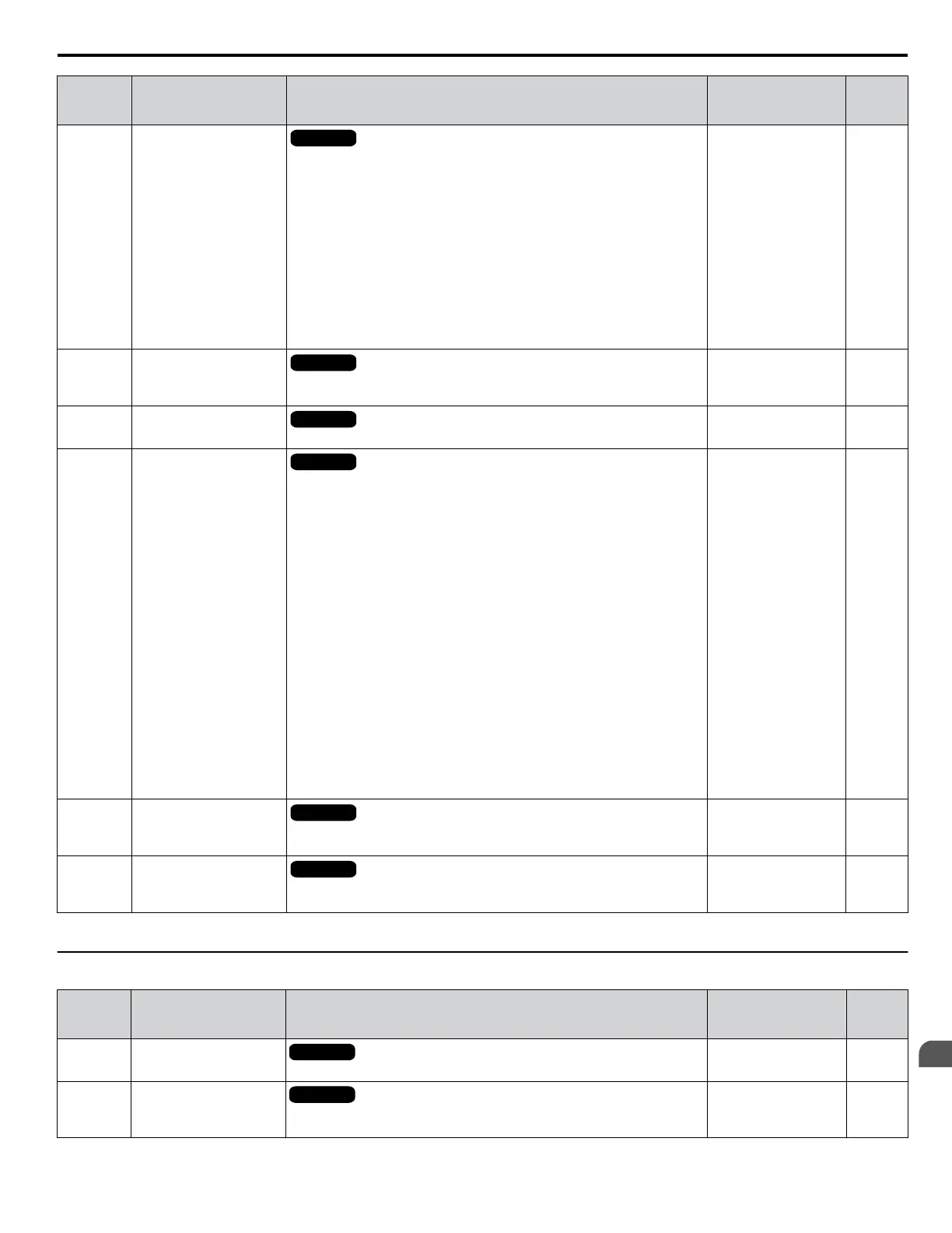
No.
(Addr.
Hex)
Name Description
Analog Output
Level
Unit
U4-18
(7DA)
Frequency Reference
Source Selection
All Modes
Displays the source for the frequency reference as XY-nn.
X: indicates which reference is used:
1 = Reference 1 (b1-01)
2 = Reference 2 (b1-15)
Y-nn: indicates the reference source
0-01 = Digital operator
1-01 = Analog (terminal A1)
1-02 = Analog (terminal A2)
1-03 = Analog (terminal A3)
2-02 to 17 = Multi-step speed (d1-02 to 17)
3-01 = MEMOBUS/Modbus communications
4-01 = Communication option card
5-01 = Pulse input
7-01 = DWEZ
No signal output
available
–
U4-19
(7DB)
Frequency Reference from
MEMOBUS/Modbus
Comm.
All Modes
Displays the frequency reference provided by MEMOBUS/Modbus
(decimal).
No signal output
available
0.01%
U4-20
(7DC)
Option Frequency
Reference
All Modes
Displays the frequency reference input by an option card (decimal).
No signal output
available
–
U4-21
(7DD)
Run Command Source
Selection
All Modes
Displays the source for the Run command as XY-nn.
X: Indicates which Run source is used:
1 = Reference 1 (b1-02)
2 = Reference 2 (b1-16)
Y: Input power supply data
0 = Digital operator
1 = External terminals
3 = MEMOBUS/Modbus communications
4 = Communication option card
7 = DWEZ
nn: Run command limit status data
00: No limit status.
01: Run command was left on when stopped in the PRG mode
02: Run command was left on when switching from LOCAL to REMOTE
operation
03: Waiting for soft charge bypass contactor after power up (Uv or Uv1
flashes after 10 s)
04: Waiting for “Run command prohibited” time period to end
05: Fast Stop (digital input, digital operator)
06: b1-17 (Run command given at power-up)
07: During baseblock while coast to stop with timer
08: Frequency reference is below minimal reference during baseblock
09: Waiting for Enter command
No signal output
available
–
U4-22
(7DE)
MEMOBUS/Modbus
Communications
Reference
All Modes
Displays the drive control data set by MEMOBUS/Modbus
communications register no. 0001H as a four-digit hexadecimal number.
No signal output
available
–
U4-23
(7DF)
Communication Option
Card Reference
All Modes
Displays drive control data set by an option card as a four-digit hexadecimal
number.
No signal output
available
–
<1> When reading the value of this monitor via MEMOBUS/Modbus, a value of 8192 is equal to 100% of the drive rated output current.
u
U5: PID Monitors
No.
(Addr.
Hex)
Name Description
Analog Output
Level
Unit
U5-01
(57)
PID Feedback
All Modes
Displays the PID feedback value.
10 V: 100% 0.01%
U5-02
(63)
PID Input
All Modes
Displays the amount of PID input (deviation between PID setpoint and
feedback).
10 V: 100% 0.01%
B.15 U: Monitors
YASKAWA ELECTRIC SIEP C710616 31B YASKAWA AC Drive – A1000 Technical Manual
453
B
Parameter List

 Loading...


