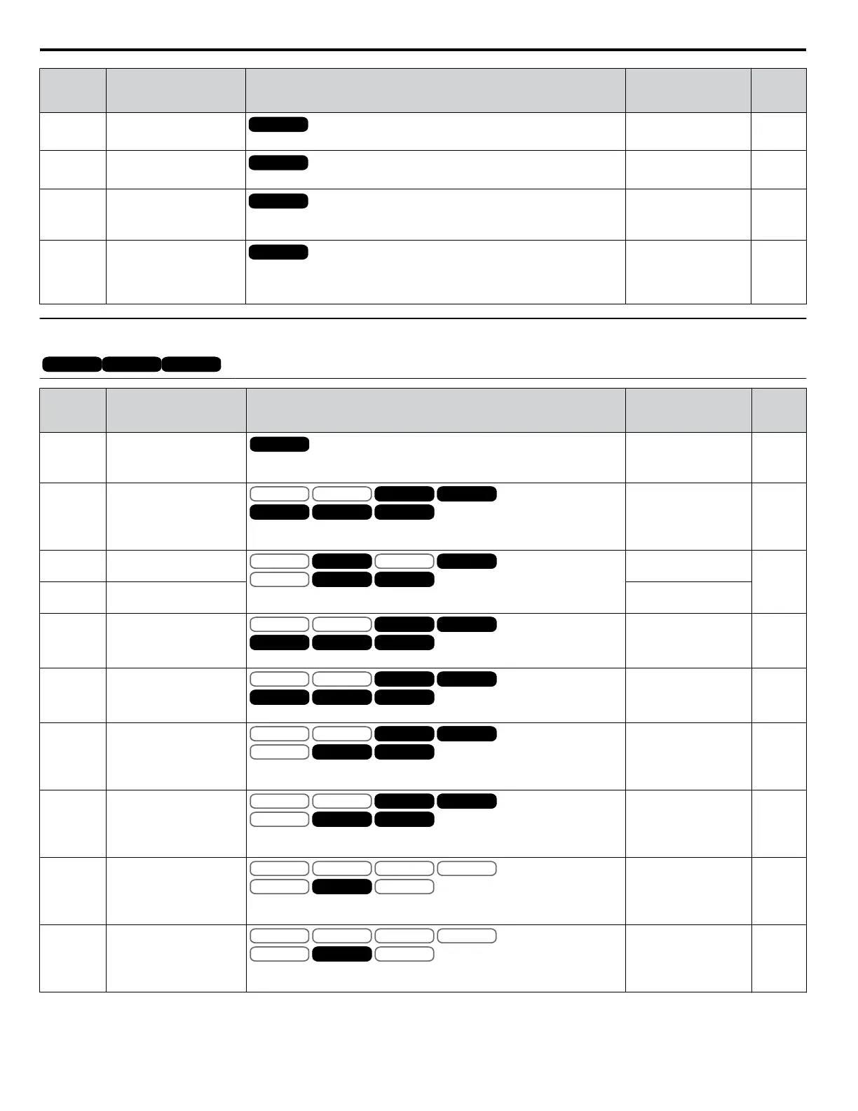
No.
(Addr.
Hex)
Name Description
Analog Output
Level
Unit
U5-03
(64)
PID Output
All Modes
Displays PID control output.
10 V: 100% 0.01%
U5-04
(65)
PID Setpoint
All Modes
Displays the PID setpoint.
10 V: 100% 0.01%
U5-05
(7D2)
PID Differential Feedback
All Modes
Displays the 2nd PID feedback value if differential feedback is used (H3-
oo = 16).
10 V: 100% 0.01%
U5-06
(7D3)
PID Adjusted Feedback
All Modes
Displays the difference of both feedback values if differential feedback is
used (U5-01 - U5-05). If differential feedback is not used, then U5-01 and
U5-06 will be the same.
10 V: 100% 0.01%
u
U6: Operation Status Monitors
OLV/PMOLV/PM AOLV/PMAOLV/PM CLV/PMCLV/PM
PM motor control modes are not available on 600 V class drives, CIMR-Ao5oooooooo.
No.
(Addr.
Hex)
Name Description
Analog Output
Level
Unit
U6-01
(51)
Motor Secondary Current
(Iq)
All Modes
Displays the value of the motor secondary current (Iq). Motor rated
secondary current is 100%.
10 V: Motor secondary
rated current
0.1%
U6-02
(52)
Motor Excitation Current
(Id)
V/f
OLV/PM
V/f w PG
AOLV/PM
OLV
CLV/PM
CLV
OLV/PM AOLV/PM
OLV
CLV/PM
CLVV/f
OLV/PM
V/f w PG
AOLV/PM
OLV
CLV/PM
CLV
OLV/PM AOLV/PM
OLV
CLV/PM
CLV
Displays the value calculated for the motor excitation current (Id). Motor
rated secondary current is 100%.
10 V: Motor secondary
rated current
0.1%
U6-03
(54)
ASR Input
V/f
OLV/PM
V/f w PG
AOLV/PM
OLV
CLV/PM
CLV
CLV/PM
CLVV/f
OLV/PM
V/f w PG
AOLV/PM
OLV
CLV/PM
CLV
CLV/PM
CLVV/f w PG
AOLV/PM
V/f w PG
AOLV/PM
Displays the input and output values when using ASR control.
10 V: Max frequency
0.01%
U6-04
(55)
ASR Output
10 V: Motor secondary
rated current
U6-05
(59)
Output Voltage Reference
(Vq)
V/f
OLV/PM
V/f w PG
AOLV/PM
OLV
CLV/PM
CLV
OLV/PM AOLV/PM
OLV
CLV/PM
CLVV/f
OLV/PM
V/f w PG
AOLV/PM
OLV
CLV/PM
CLV
OLV/PM AOLV/PM
OLV
CLV/PM
CLV
Output voltage reference (Vq) for the q-Axis.
10 V: 575 Vrms 0.1 Vac
U6-06
(5A)
Output Voltage Reference
(Vd)
V/f
OLV/PM
V/f w PG
AOLV/PM
OLV
CLV/PM
CLV
OLV/PM AOLV/PM
OLV
CLV/PM
CLVV/f
OLV/PM
V/f w PG
AOLV/PM
OLV
CLV/PM
CLV
OLV/PM AOLV/PM
OLV
CLV/PM
CLV
Output voltage reference (Vd) for the d-Axis.
10 V: 575 Vrms 0.1 Vac
U6-07
(5F)
q-Axis ACR Output
V/f
OLV/PM
V/f w PG
AOLV/PM
OLV
CLV/PM
CLV
AOLV/PM
OLV
CLV/PM
CLVV/f
OLV/PM
V/f w PG
AOLV/PM
OLV
CLV/PM
CLV
AOLV/PM
OLV
CLV/PM
CLV
Displays the output value for current control relative to motor secondary
current (q-Axis).
10 V: 575 Vrms 0.1%
U6-08
(60)
d-Axis ACR Output
V/f
OLV/PM
V/f w PG
AOLV/PM
OLV
CLV/PM
CLV
AOLV/PM
OLV
CLV/PM
CLVV/f
OLV/PM
V/f w PG
AOLV/PM
OLV
CLV/PM
CLV
AOLV/PM
OLV
CLV/PM
CLV
Displays the output value for current control relative to motor secondary
current (d-Axis).
10 V: 575 Vrms 0.1%
U6-09
(7C0)
Advance Phase
Compensation (Δ θ)
V/f
OLV/PM
V/f w PG
AOLV/PM
OLV
CLV/PM
CLV
AOLV/PM
V/f
OLV/PM
V/f w PG
AOLV/PM
OLV
CLV/PM
CLV
AOLV/PM
Displays the degree of forward phase correction after calculating the
deviation of Δθcmp.
10 V: 180 deg
-10 V: -180 deg
0.1 deg
U6-10
(7C1)
Control Axis Deviation
(Δθ)
V/f
OLV/PM
V/f w PG
AOLV/PM
OLV
CLV/PM
CLV
AOLV/PM
V/f
OLV/PM
V/f w PG
AOLV/PM
OLV
CLV/PM
CLV
AOLV/PM
Displays the amount of deviation between the actual d-Axis / q-Axis and
the γ-Axis / δ-Axis used for motor control.
10 V: 180 deg
-10 V: -180 deg
0.1 deg
B.15 U: Monitors
454
YASKAWA ELECTRIC SIEP C710616 31B YASKAWA AC Drive – A1000 Technical Manual

 Loading...


