6.6 Operator Programming Errors
u
Operator Programming Error Codes, Causes, and Possible Solutions
An Operator Programming Error (oPE) occurs when a contradictory parameter is set or an individual parameter is set to an
inappropriate value.
The drive will not operate until the parameter or parameters causing the problem are set correctly. An oPE, however, does not
trigger an alarm or fault output. If an oPE occurs, investigate the cause and refer to Table 6.16 for the appropriate action. When
an oPE appears on the operator display, press the ENTER button to view U1-18 and see which parameter is causing the oPE.
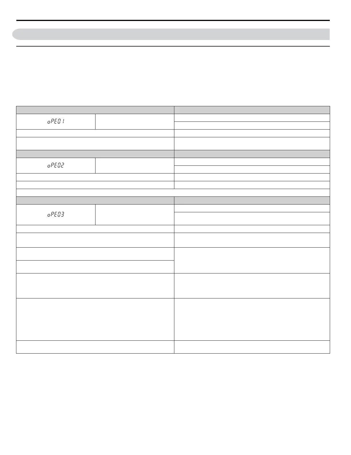
Table 6.16 oPE Codes, Causes, and Possible Solutions
Digital Operator Display Error Name
oPE01
Drive Capacity Setting Fault
Drive capacity and the value set to o2-04 do not match.
Cause Possible Solutions
The drive model selection (o2-04) and the actual capacity of the drive are
not the same.
Correct the value set to o2-04.
Digital Operator Display Error Name
oPE02
Parameter Range Setting Error
Use U1-18 to find parameters set outside the range.
Cause Possible Solutions
Parameters were set outside the possible setting range. Set parameters to the proper values.
Note: When multiple errors occur at the same time, other errors are given precedence over oPE02.
Digital Operator Display Error Name
oPE03
Multi-Function Input Selection Error
A contradictory setting is assigned to multi-function contact inputs H1-01
to H1-08.
Cause Possible Solutions
• The same function is assigned to two multi-function inputs.
• Excludes “Not used” and “External Fault.”
• Ensure all multi-function inputs are assigned to different functions.
• Re-enter the multi-function settings to ensure this does not occur.
The Up command was set but the Down command was not, or vice versa
(settings 10 vs. 11).
Correctly set functions that need to be enabled in combination with other
functions.
The Up 2 command was set but the Down 2 command was not, or vice versa
(settings 75 vs. 76).
•
Run/Stop command for a 2-wire sequence was set (H1-oo = 42), but
Forward/Reverse command (H1-oo = 43) was not.
• “Drive Enable” is set to multi-function input S1 or S2 (H1-01 = 6A or
H1-02 = 6A).
Correctly set functions that need to be enabled in combination with other
functions.
Two of the following functions are set at the same time:
• Up/Down Command (10 vs. 11)
• Up 2/Down 2 Command (75 vs. 76)
• Hold Accel/Decel Stop (A)
• Analog Frequency Reference Sample/Hold (1E)
• Offset Frequency 1, 2, 3 Calculations (44, 45, 46)
• Check if contradictory settings have been assigned to the multi-function
input terminals at the same time.
• Correct setting errors.
The Up/Down command (10, 11) is enabled at the same time as PID control
(b5-01).
Disable control PID (b5-01 = 0) or disable the Up/Down command.
6.6 Operator Programming Errors
324
YASKAWA ELECTRIC SIEP C710616 31B YASKAWA AC Drive – A1000 Technical Manual

 Loading...


