3.4 Terminal Block Configuration
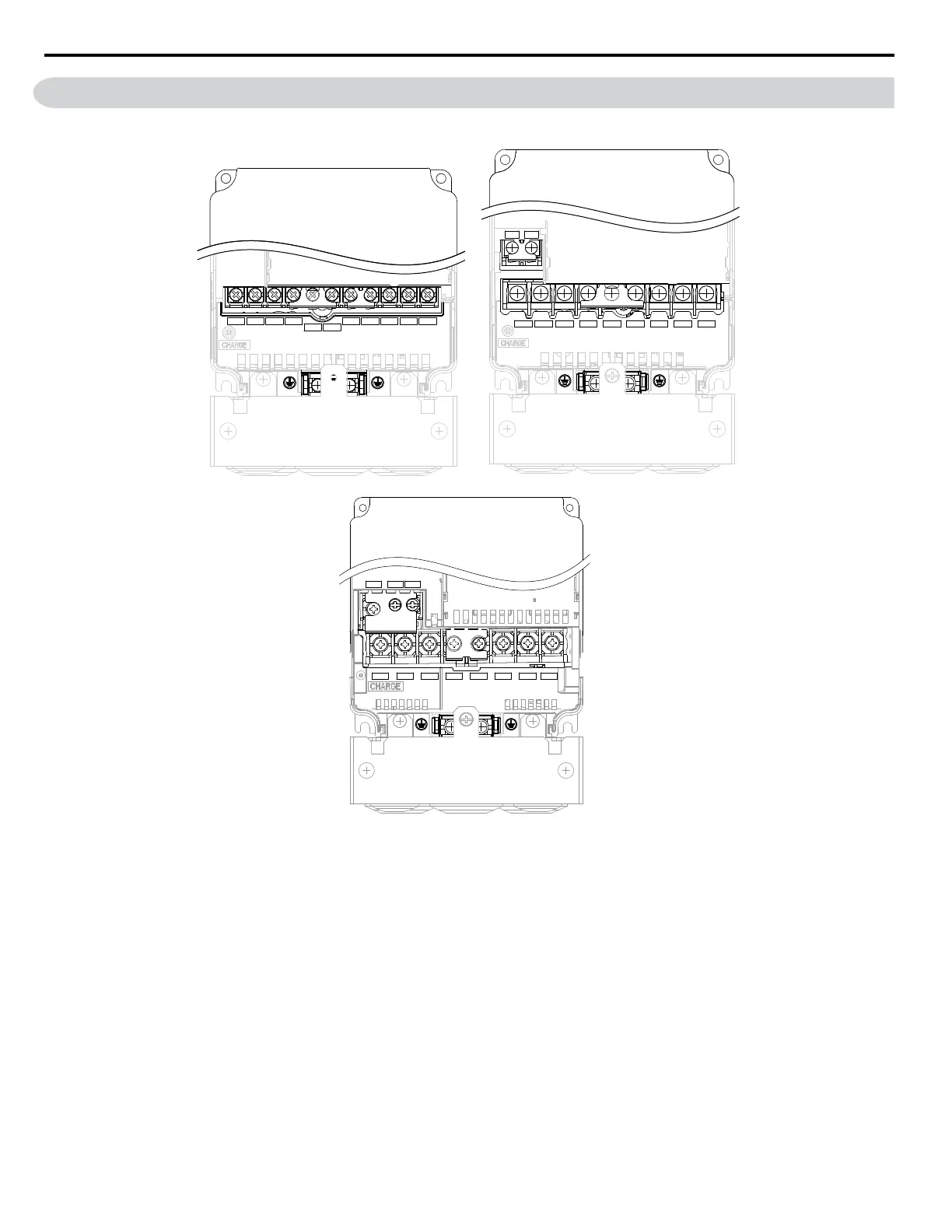
Figure 3.3 shows the different main circuit terminal arrangements for the drive capacities.
CIMR-A5A0003, 0004, 0006, 0009
R/L1
S/L2
T/L3
_
+1
+2
B1
B2
U/T1
V/T2
W/T3
R/L1
S/L2
T/L3
_
1
2
U/T1
V/T2
W/T3
B1
B2
CIMR-A5A0011
R/L1 S/L2 T/L3 U/T1 V/T2 W/T3
+1 +2
B1 B2
–
CIMR-Ao5A0017, 0022, 0027, 0032
Figure 3.3 Main Circuit Terminal Block Configuration
3.4 Terminal Block Configuration
54
YASKAWA ELECTRIC SIEP C710616 31B YASKAWA AC Drive – A1000 Technical Manual

 Loading...


