Setting 0: Disabled
The drive uses the frequency reference to determine the direction of motor rotation to restart the motor.
Setting 1: Enabled
The drive detects the motor rotation direction to restart the motor.
n
b3-17: Speed Search Restart Current Level
Sets the current level at which Speed Estimation is restarted as a percentage of drive rated current to avoid overcurrent and
overvoltage problems since a large current can flow into the drive if the difference between the estimated frequency and the
actual motor speed is too big when performing Speed Estimation.
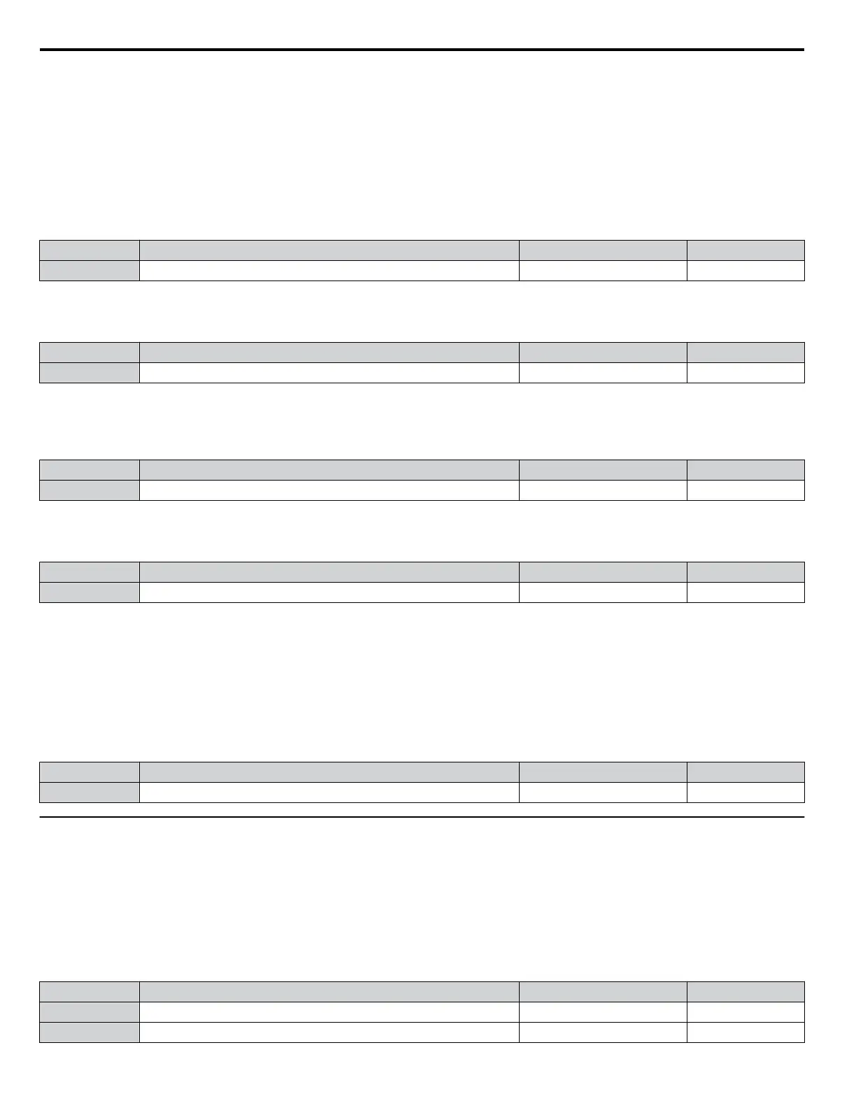
No. Name Setting Range Default
b3-17 Speed Search Restart Current Level 0 to 200% 150%
n
b3-18: Speed Search Restart Detection Time
Sets the time for which the current must be above the level set in b3-17 before restarting Speed Search.
No. Name Setting Range Default
b3-18 Speed Search Restart Detection Time 0.00 to 1.00 s 0.10 s
n
b3-19: Number of Speed Search Restarts
Sets the number of times the drive should attempt to find the speed and restart the motor. If the number of restart attempts
exceeds the value set to b3-19, the SEr fault will occur and the drive will stop.
No. Name Setting Range Default
b3-19 Number of Speed Search Restarts 0 to 10 3
n
b3-24: Speed Search Method Selection
Sets the Speed Search method used.
No. Parameter Name Setting Range Default
b3-24 Speed Search Method Selection 0, 1 0
Setting 0: Current Detection Speed Search
Setting 1: Speed Estimation Speed Search
Note: Refer to Current Detection Speed Search (b3-24 = 0) on page 136 and Refer to Speed Estimation Type Speed Search (b3-24 = 1) on page
137 for explanations of the Speed Search methods.
n
b3-25: Speed Search Wait Time
Sets the wait time between Speed Search restarts. Increase the wait time if problems occur with overcurrent, overvoltage, or
if the SEr fault occurs.
No. Name Setting Range Default
b3-25 Speed Search Wait Time 0.0 to 30.0 s 0.5 s
u
b4: Delay Timers
The timer function is independent of drive operation and can delay the switching of a digital output triggered by a digital input
signal and help eliminate chattering switch noise from sensors. An on-delay and off-delay can be set separately.
To enable the timer function, set a multi-function input to “Timer input” (H1-oo = 18) and set a multi-function output to
“Timer output” (H2-oo = 12). Only one timer can be used.
n
b4-01, b4-02: Timer Function On-Delay, Off-Delay Time
b4-01 sets the on-delay time for switching the timer output. b4-02 sets the off-delay time for switching the timer output.
No. Name Setting Range Default
b4-01 Timer Function On-Delay Time 0.0 to 3000.0 s 0.0 s
b4-02 Timer Function Off-Delay Time 0.0 to 3000.0 s 0.0 s
5.2 b: Application
140
YASKAWA ELECTRIC SIEP C710616 31B YASKAWA AC Drive – A1000 Technical Manual

 Loading...


