E.2 Basic Parameter Settings
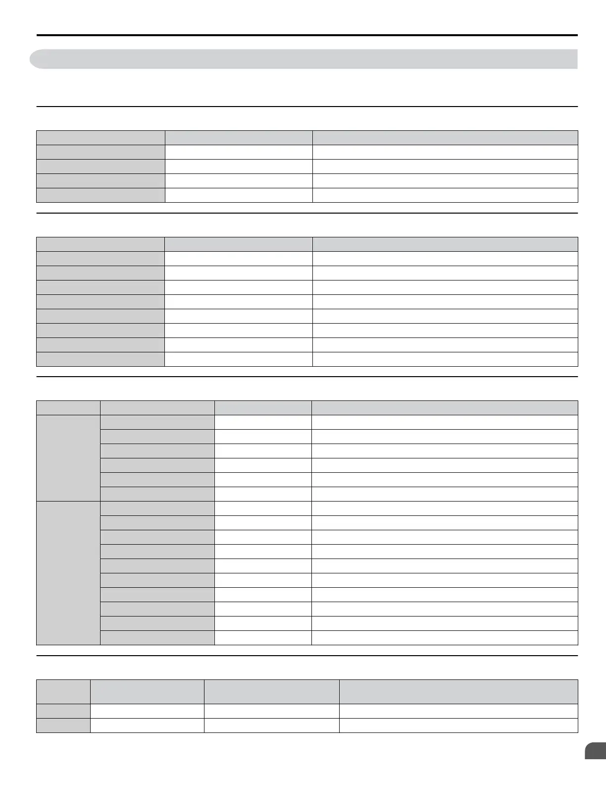
Use the following tables to keep records of the most important parameters. Have these data available when contacting Yaskawa
technical support.
u
Basic Setup
Item Setting Value Memo
Control Mode A1-02 =
Normal/Heavy Duty Selection C6-01 =
Frequency Reference Source b1-01 =
Run Command Source b1-02 =
u
V/f Pattern Setup
Item Setting Value Memo
V/f Pattern Selection E1-03 =
Max. Output Frequency E1-04 =
Max. Voltage E1-05 =
Base Frequency E1-06 =
Mid. Output Frequency E1-07 =
Mid. Output Frequency Volt. E1-08 =
Min. Output Frequency E1-09 =
Min. Output Frequency Volt. E1-10 =
u
Motor Setup
Motor Type Item Setting Value Memo
Induction
Motor Rated Current E2-01 =
Motor Rated Slip E2-02 =
Motor No-Load Current E2-03 =
No. of Motor Poles E2-04 =
Line-to-Line Resistance E2-05 =
Motor Leakage Inductance E2-06 =
Permanent
Magnet
Motor Code Selection E5-01 =
Motor Rated Power E5-02 =
Motor Rated Current E5-03 =
No. of Motor Poles E5-04 =
Motor Stator Resistance E5-05 =
Motor d-Axis Inductance E5-06 =
Motor q-Axis Inductance E5-07 =
Induction Volt. Const. 1 E5-09 =
Encoder Z-pulse Offset E5-11 =
Induction Volt. Const. 2 E5-24 =
u
Multi-Function Digital Inputs
Terminal Input Used
Setting Value
and Function Name
Memo
S1 H1-01 =
S2 H1-02 =
E.2 Basic Parameter Settings
YASKAWA ELECTRIC SIEP C710616 31B YASKAWA AC Drive – A1000 Technical Manual
507
E
Quick Reference Sheet

 Loading...


