n
Three-Phase 600 V Class
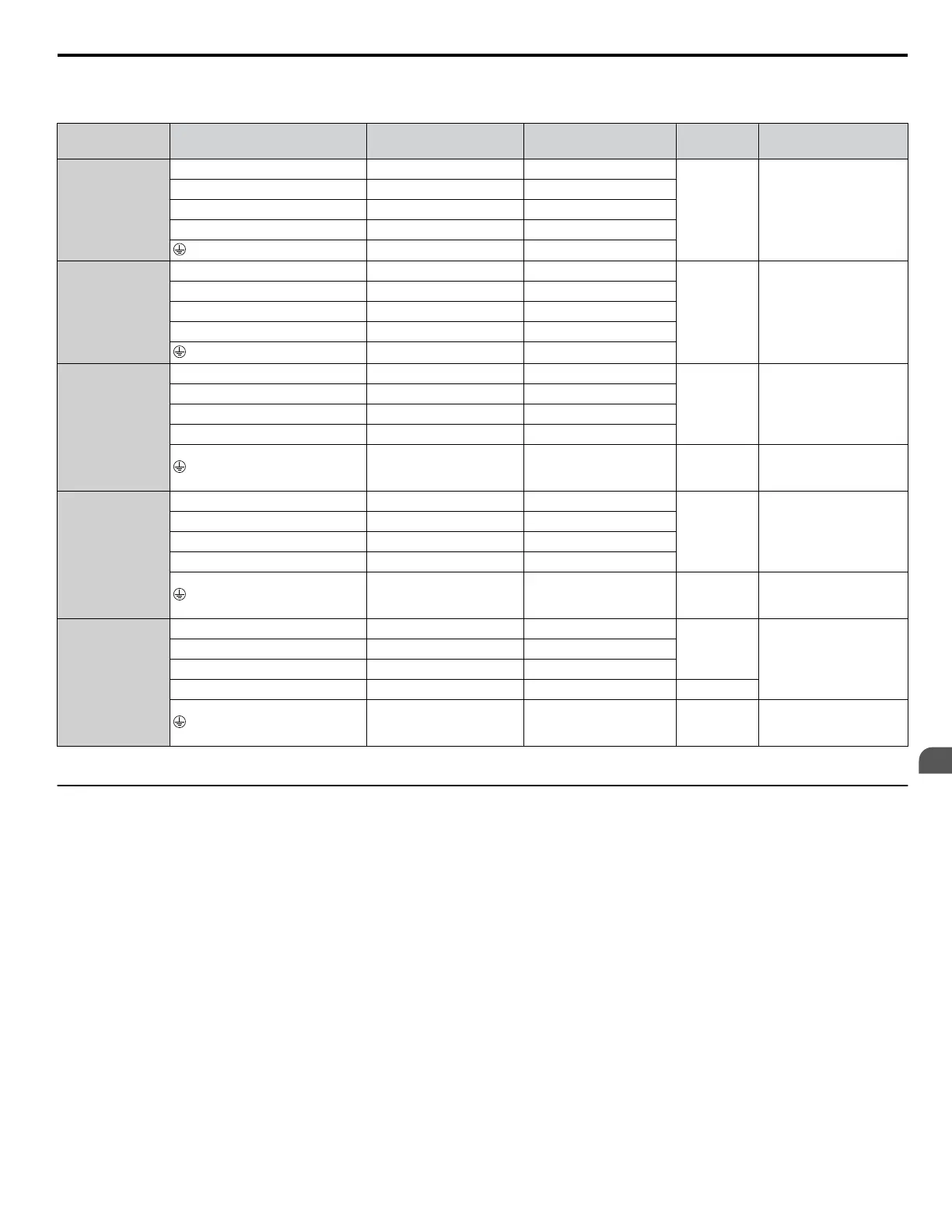
Table 3.2 Wire Gauge and Torque Specifications (Three-Phase 600 V Class)
Model CIMR-Ao
Terminal
Recomm. Gauge AWG,
kcmil
<1>
Applicable Gauge
AWG, kcmil
<1>
Size
Tightening Torque
N·m (lb.in.)
5A0003
5A0004
R/L1, S/L2, T/L3 14 14 to 10
M4
1.2 to 1.5
(10.6 to
13.3)
U/T1, V/T2, W/T3 14 14 to 10
–, +1, +2 – 14 to 10
B1, B2 – 14 to 10
10 14 to 10
5A0006
5A0009
R/L1, S/L2, T/L3 12 14 to 10
M4
1.2 to 1.5
(10.6 to
13.3)
U/T1, V/T2, W/T3 14 14 to 10
–, +1, +2 – 14 to 10
B1, B2 – 14 to 10
10 14 to 10
5A0011
R/L1, S/L2, T/L3 10 10 to 6
M4
1.2 to 1.5
(10.6 to
13.3)
U/T1, V/T2, W/T3 10 10 to 6
–, +1, +2 – 12 to 6
B1, B2 – 12 to 10
10 12 to 10 M5
2 to 2.5
(17.7 to
22.1)
5A0017
5A0022
R/L1, S/L2, T/L3 6 8 to 6
M5
2 to 2.5
(17.7 to
22.1)
U/T1, V/T2, W/T3 8 8 to 6
–, +1, +2 – 6
B1, B2 – 10 to 8
6 10 to 6 M6
4 to 6
(35.4 to
53.1)
5A0027
5A0032
R/L1, S/L2, T/L3 6 6 to 4
M6
2 to 2.5
(17.7 to
22.1)
U/T1, V/T2, W/T3 6 6 to 4
–, +1, +2 – 6 to 4
B1, B2 – 10 to 8 M5
6 8 to 6 M6
4 to 6
(35.4 to
53.1)
<1> Gauges listed in Table 3.2 are for use in the United States.
u
Main Circuit Terminal and Motor Wiring
This section outlines the various steps, precautions, and checkpoints for wiring the main circuit terminals and motor terminals.
NOTICE: When connecting the motor to the drive output terminals U/T1, V/T2, and W/T3, the phase order for the drive and motor should
match. Failure to comply with proper wiring practices may cause the motor to run in reverse if the phase order is backward.
NOTICE: Do not connect phase-advancing capacitors or LC/RC noise filters to the output circuits. Failure to comply could result in damage
to the drive, phase-advancing capacitors, LC/RC noise filters or ground fault circuit interrupters.
NOTICE: Do not connect the AC power line to the output motor terminals of the drive. Failure to comply could result in death or serious
injury by fire as a result of drive damage from line voltage application to output terminals.
n
Cable Length Between Drive and Motor
Voltage drop along the motor cable may cause reduced motor torque when the wiring between the drive and the motor is too
long, especially at low frequency output. This can also be a problem when motors are connected in parallel with a fairly long
motor cable. Drive output current will increase as the leakage current from the cable increases. An increase in leakage current
may trigger an overcurrent situation and weaken the accuracy of the current detection.
Adjust the drive carrier frequency according to Table 3.3. If the motor wiring distance exceeds 100 m because of the system
configuration, reduce the ground currents. Refer to C6-02: Carrier Frequency Selection on page 167.
3.8 Main Circuit Wiring
YASKAWA ELECTRIC SIEP C710616 31B YASKAWA AC Drive – A1000 Technical Manual
59
3
Electrical Installation

 Loading...


