Table 3.3 Cable Length Between Drive and Motor
Cable Length 50 m or less 100 m or less Greater than 100 m
Carrier Frequency 15 kHz or less 5 kHz or less 2 kHz or less
Note: When setting carrier frequency in a drive running multiple motors, calculate the cable length as the total distance of wiring to all motors that
are connected.
n
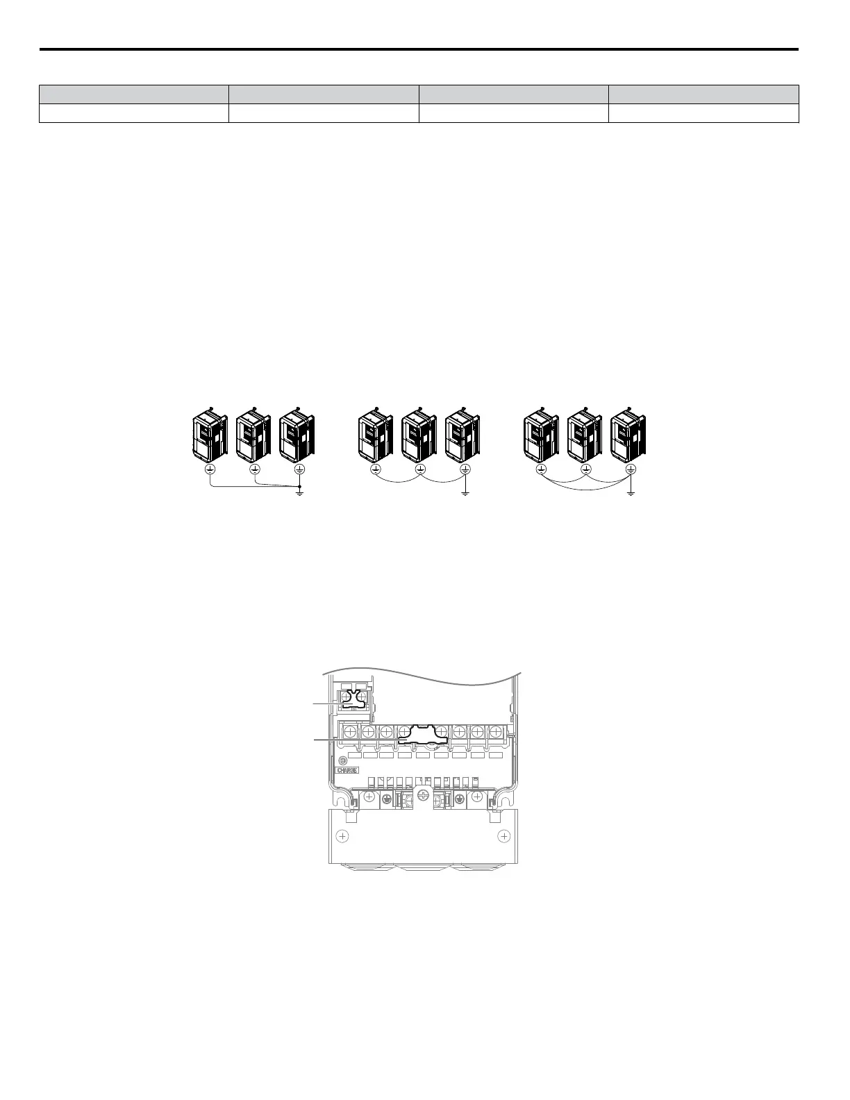
Ground Wiring
Follow the precautions to wire the ground for one drive or a series of drives.
WARNING! Electrical
Shock Hazard. Always use a ground wire that complies with technical standards on electrical equipment and minimize
the length of the ground wire. Improper equipment grounding may cause dangerous electrical potentials on equipment chassis, which could
result in death or serious injury.
WARNING! Electrical Shock Hazard. Be sure to ground the drive ground terminal. Improper equipment grounding could result in death or
serious injury by contacting ungrounded electrical equipment.
NOTICE: Do not share the ground wire with other devices such as welding machines or large-current electrical equipment. Improper
equipment grounding could result in drive or equipment malfunction due to electrical interference.
NOTICE: When using more than one drive, ground multiple drives according to instructions. Improper equipment grounding could result in
abnormal operation of drive or equipment.
Refer to Figure 3.12 when using multiple drives. Do not loop the ground wire.
OK OK NOT OK
Figure 3.12 Multiple Drive Wiring
n
Wiring the Main Circuit Terminal
WARNING! Electrical
Shock Hazard. Shut off the power supply to the drive before wiring the main circuit terminals. Failure to comply may
result in death or serious injury.
Wire the main circuit terminals after the terminal board has been properly grounded.
The drive has a cover placed over the DC bus and braking circuit terminals prior to shipment to help prevent miswiring. Use
wire cutters to cut away covers as needed for terminals.
R/L1
S/L2
T/L3
_
1
2
U/T1
V/T2
W/T3
B1
B2
A
B
A – Braking circuit protective cover B – DC bus protective cover
Figure 3.13 Protecting Cover to Prevent Miswiring (CIMR-Ao5A0011)
n
Main Circuit Connection Diagram
Refer to Main Circuit Connection Diagram on page 53 when wiring terminals on the main power circuit of the drive.
WARNING! Fire
Hazard. The braking resistor connection terminals are B1 and B2. Do not connect braking resistors to any other terminals.
Improper wiring connections could cause the braking resistor to overheat and cause death or serious injury by fire. Failure to comply may
result in damage to the braking circuit or drive.
3.8 Main Circuit Wiring
60
YASKAWA ELECTRIC SIEP C710616 31B YASKAWA AC Drive – A1000 Technical Manual

 Loading...


