No. Parameter Name Setting Range Default
H2-06 Watt Hour Output Unit Selection
0: 0.1 kWh units
1: 1 kWh units
2: 10 kWh units
3: 100 kWh units
4: 1000 kWh units
0
Note: 1. A negative power output (i.e., regeneration) does not subtract from the total watt hours.
2. The drive keeps track of the watt hours as long as the control circuit has power. The value is reset when the power supply is shut off.
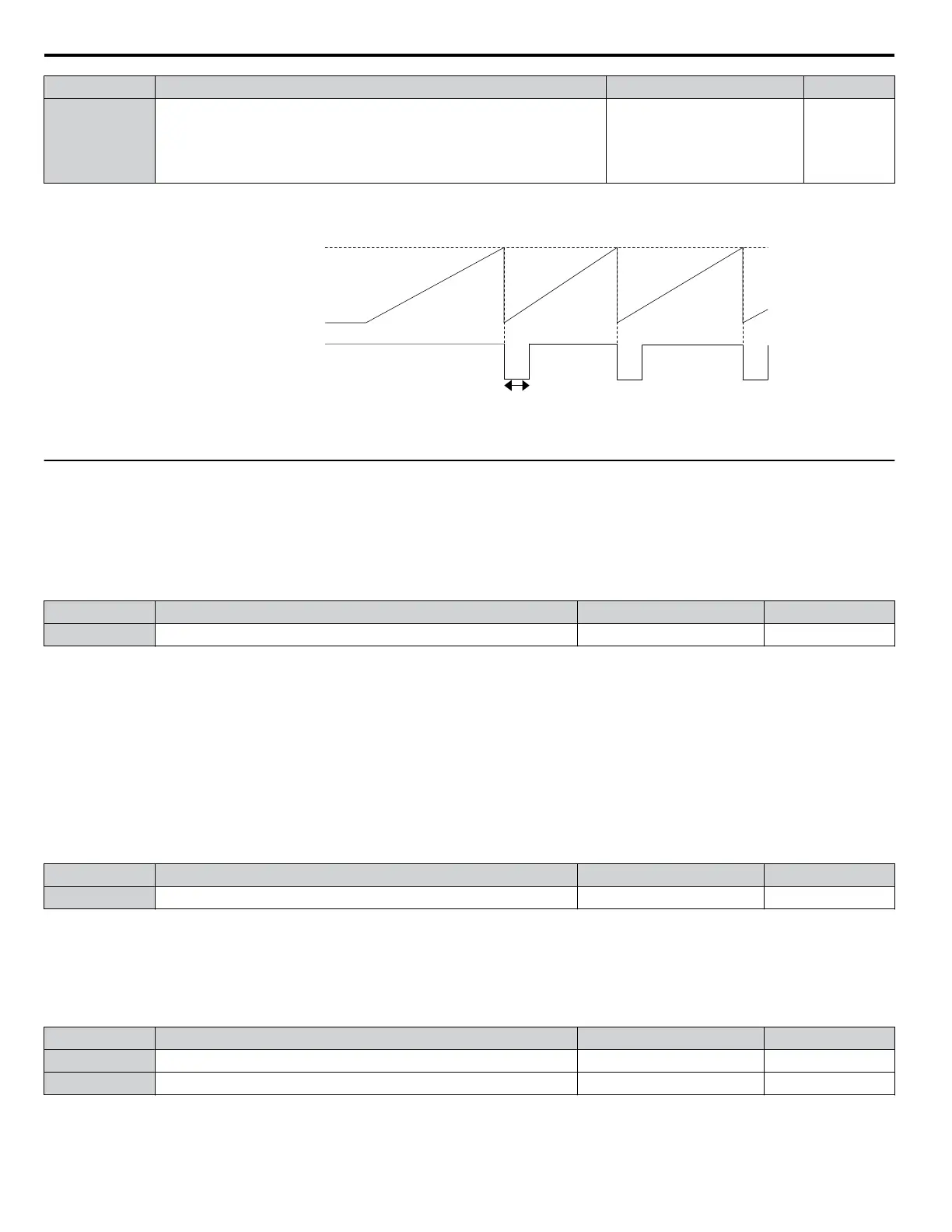
0.2 s
H2-06
(Pulse Output Unit)
H2-01 to 03
(Multi-function Output)
Integral Power (every 100 ms)
OFF OFF
ON
Figure 5.77 Watt Hour Output Example
u
H3: Multi-Function Analog Inputs
The drive is equipped with three multi-function analog input terminals: A1, A2, and A3. Refer to Multi-Function Analog
Input Terminal Settings on page 231 for a listing of the functions that can be set to these terminals.
n
H3-01: Terminal A1 Signal Level Selection
Selects the input signal level for analog input A1.
No. Name Setting Range Default
H3-01 Terminal A1 Signal Level Selection 0 to 1 0
Setting 0: 0 to 10 Vdc
The input level is 0 to 10 Vdc. The minimum input level is limited to 0%, so that a negative input signal due to gain and bias
settings will be read as 0%.
Setting 1: -10 to 10 Vdc
The input level is -10 to 10 Vdc. If the resulting voltage is negative after being adjusted by gain and bias settings, then the
motor will rotate in reverse.
n
H3-02: Terminal A1 Function Selection
Selects the input signal level for analog input A3. Refer to Multi-Function Analog Input Terminal Settings on page 231 for
instructions on adjusting the signal level.
No. Name Setting Range Default
H3-02 Terminal A1 Function Selection 0 to 31 0
n
H3-03, H3-04: Terminal A1 Gain and Bias Settings
Parameter H3-03 sets the level of the selected input value that is equal to 10 Vdc input at terminal A1 (gain).
Parameter H3-04 sets the level of the selected input value that is equal to 0 V input at terminal A1 (bias).
Use both parameters to adjust the characteristics of the analog input signal to terminal A1.
No. Name Setting Range Default
H3-03 Terminal A1 Gain Setting -999.9 to 999.9% 100.0%
H3-04 Terminal A1 Bias Setting -999.9 to 999.9% 0.0%
Setting Examples
• Gain H3-03 = 200%, bias H3-04 = 0, terminal A1 as frequency reference input (H3-02 = 0):
5.7 H: Terminal Functions
228
YASKAWA ELECTRIC SIEP C710616 31B YASKAWA AC Drive – A1000 Technical Manual

 Loading...


