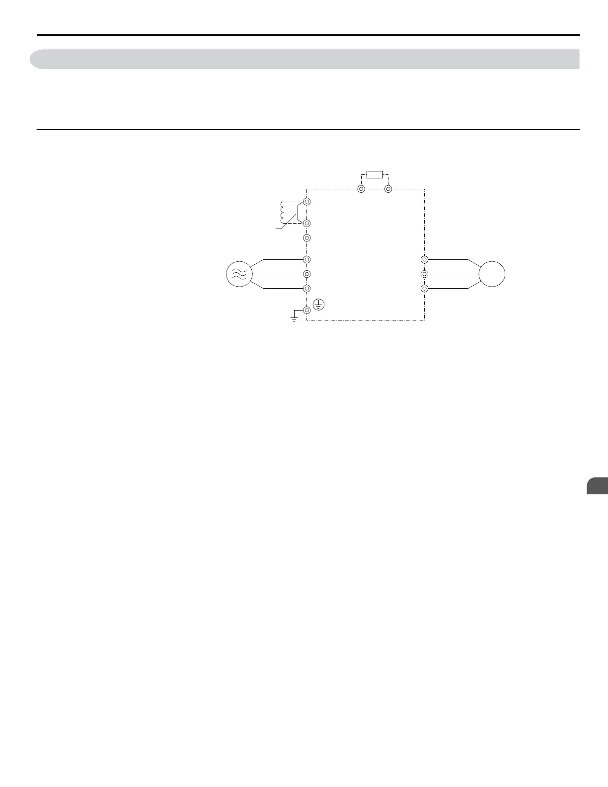
3.3 Main Circuit Connection Diagram
Refer to diagrams in this section when wiring the main circuit of the drive. Connections may vary based on drive capacity.
The DC power supply for the main circuit also provides power to the control circuit.
NOTICE: Do not use the negative DC bus terminal “–” as a ground terminal. This terminal is at high DC voltage potential. Improper wiring
connections could damage the drive.
u
Three-Phase 600 V Class
Braking Resistor Unit
(option)
Drive
Motor
Jumper
DC reactor
(option)
B1
+1
R/L1
S/L2
T/L3
U/T1
V/T2
W/T3
+2
−
B2
Three-Phase power supply
500 to 600 Vac, 50 to 60 Hz
Figure 3.2 Connecting Main Circuit Terminals
3.3 Main Circuit Connection Diagram
YASKAWA ELECTRIC SIEP C710616 31B YASKAWA AC Drive – A1000 Technical Manual
53
3
Electrical Installation

 Loading...


