• Lower n3-13 when flux saturation characteristics cause overcurrent. A high setting sometimes causes overcurrent (oC),
motor overload (oL1), or drive overload (oL2). Lowering n3-21 can also help remedy these problems.
n
n3-14: High Frequency Injection during Overexcitation Deceleration
Enables High Frequency Injection while Overexcitation Deceleration is executed. Injecting high frequency into the motor
increases loss and shortens deceleration time. This function tends to increase audible noise from the motor, and may not be
desirable in environments where motor noise is a concern.
No. Name Setting Range Default
n3-14 High Frequency Injection During Overexcitation Deceleration 0, 1 0
Setting 0: Disabled
Setting 1: Enabled
n
n3-21: High Slip Suppression Current Level
If the motor current exceeds the value set to n3-21 during Overexcitation Deceleration due to flux saturation, the drive
automatically reduces the overexcitation gain. Parameter n3-21 is set as a percentage of the drive rated current.
Set this parameter to a relatively low value to optimize deceleration. If overcurrent, oL1, or oL2 occur during Overexcitation
Deceleration, reduce the overslip suppression current level.
No. Name Setting Range Default
n3-21 High Slip Suppression Current Level 0 to 150% 100%
n
n3-23: Overexcitation Operation Selection
Limits the Overexcitation Deceleration operation selected in parameter L3-04 to forward only or reverse only.
No. Name Setting Range Default
n3-23 Overexcitation Operation Selection 0 to 2 0
Setting 0: Overexcitation Operation as Selected in L3-04 in Forward and Reverse Direction
Setting 1: Overexcitation Operation as Selected in L3-04 in Forward Direction Only
Setting 2: Overexcitation Operation as Selected in L3-04 in Reverse Direction Only
u
n5: Feed Forward Control
Note:
PM motor control modes are not available on 600 V class drives, CIMR-Ao5oooooooo.
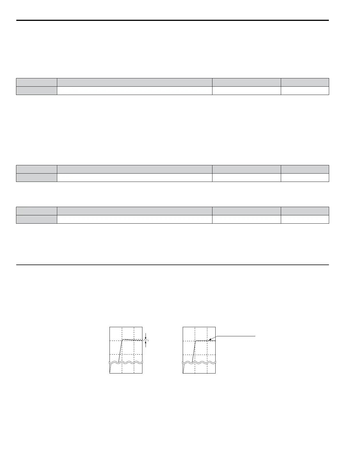
Enabling Feed Forward improves the responsiveness of the drive to speed reference changes in applications where a high
speed control proportional gain setting (ASR gain, C5-01, C5-03) would lead to problems with overshoot, undershoot, or
oscillation. Figure 5.105 gives an example of overshoot reduction by Feed Forward. Parameters related to this function and
the function principle are illustrated in Figure 5.106. Feed Forward can only be used in CLV, CLV/PM, or AOLV/PM (A1-02
= 4, 6, or 7).
1050
Overshoot
Conventional Speed Control Feed Forward Control
Time (s)
Motor Speed (r/min)
Motor Speed (r/min)
Time (s)
900
750
0
1050
900
750
0
0 0.5 1 0 0.5 1
Suppresses
overshoot at the
end of acceleration
Figure 5.105 Overshoot Suppression by Feed Forward Control
5.9 n: Special Adjustments
272
YASKAWA ELECTRIC SIEP C710616 31B YASKAWA AC Drive – A1000 Technical Manual

 Loading...


