5.5 E: Motor Parameters
E parameters cover V/f pattern and motor data settings.
u
E1: V/f Pattern for Motor 1
n
E1-01: Input Voltage Setting
Adjusts the levels of some protective features of the drive (overvoltage, Stall Prevention, etc.). Set this parameter to the nominal
voltage of the AC power supply.
NOTICE: Set parameter E1-01 to match the input voltage of the drive. Drive input voltage (not motor voltage) must be set in E1-01 for the
protective features to function properly. Failure to set the correct drive input voltage will result in improper drive operation.
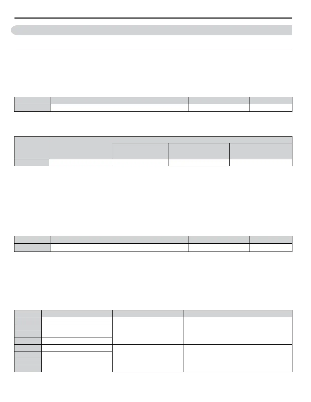
No. Parameter Name Setting Range Default
E1-01 Input Voltage Setting 446 to 733 V 575 V
E1-01 Related Values
The input voltage setting determines the overvoltage and undervoltage detection levels, the operation levels of the braking
transistor, the KEB function, and the overvoltage suppression function.
Voltage Setting Value of E1-01
(Approximate Values)
Uv Detection Level
(L2-05)
Desired DC Bus Voltage
during KEB (L2-11)
ov Suppression /
Stall Prevention Level
(L3-17)
600 V Class All settings 475 V 635 V 930 V
Note: The braking transistor operation levels are valid for the drive internal braking transistor. When using an external CDBR braking chopper, refer
to the instruction manual of that unit.
n
V/f Pattern Settings (E1-03)
The drive uses a V/f pattern to adjust the output voltage relative to the frequency reference. There are 15 different predefined
V/f patterns (setting 0 to E) from which to select, each with varying voltage profiles, saturation levels (frequency at which
maximum voltage is reached), and maximum frequencies. Additionally, one custom V/f pattern is available (setting F) that
requires the user to create the pattern using parameters E1-04 through E1-10.
n
E1-03: V/f Pattern Selection
Selects the V/f pattern for the drive and motor from 15 predefined patterns or creates a custom V/f pattern.
No. Parameter Name Setting Range Default
E1-03 V/f Pattern Selection
0 to F
<1>
F
<2>
<1> In OLV, only setting F is available.
<2> Parameter setting value is not reset to the default value during drive initialization (A1-03).
Setting a Predefined V/f Pattern (Setting 0 to E)
Choose the V/f pattern that best meets the application demands from the table below. These settings are available only in
V/f Control modes. Set the correct value to E1-03. Parameters E1-04 to E1-13 can only be monitored, not changed.
Note: 1. Setting an improper V/f pattern may result in low motor torque or increased current due to overexcitation.
2. Drive initialization does not reset parameter E1-03.
Table 5.21 Predefined V/f Patterns
Setting Specification Characteristic Application
0 50 Hz
Constant torque
For general purpose applications. Torque remains constant
regardless of changes to speed.
1 60 Hz
2 60 Hz (with 50 Hz base)
3 72 Hz (with 60 Hz base)
4 50 Hz, Heavy Duty 2
Derated torque
For fans, pumps, and other applications that require torque
derating relative to the load.
5 50 Hz, Heavy Duty 1
6 50 Hz, Heavy Duty 1
7 50 Hz, Heavy Duty 2
5.5 E: Motor Parameters
184
YASKAWA ELECTRIC SIEP C710616 31B YASKAWA AC Drive – A1000 Technical Manual

 Loading...


