4.11 Test Run Checklist
Review the checklist before performing a test run. Check each item that applies.
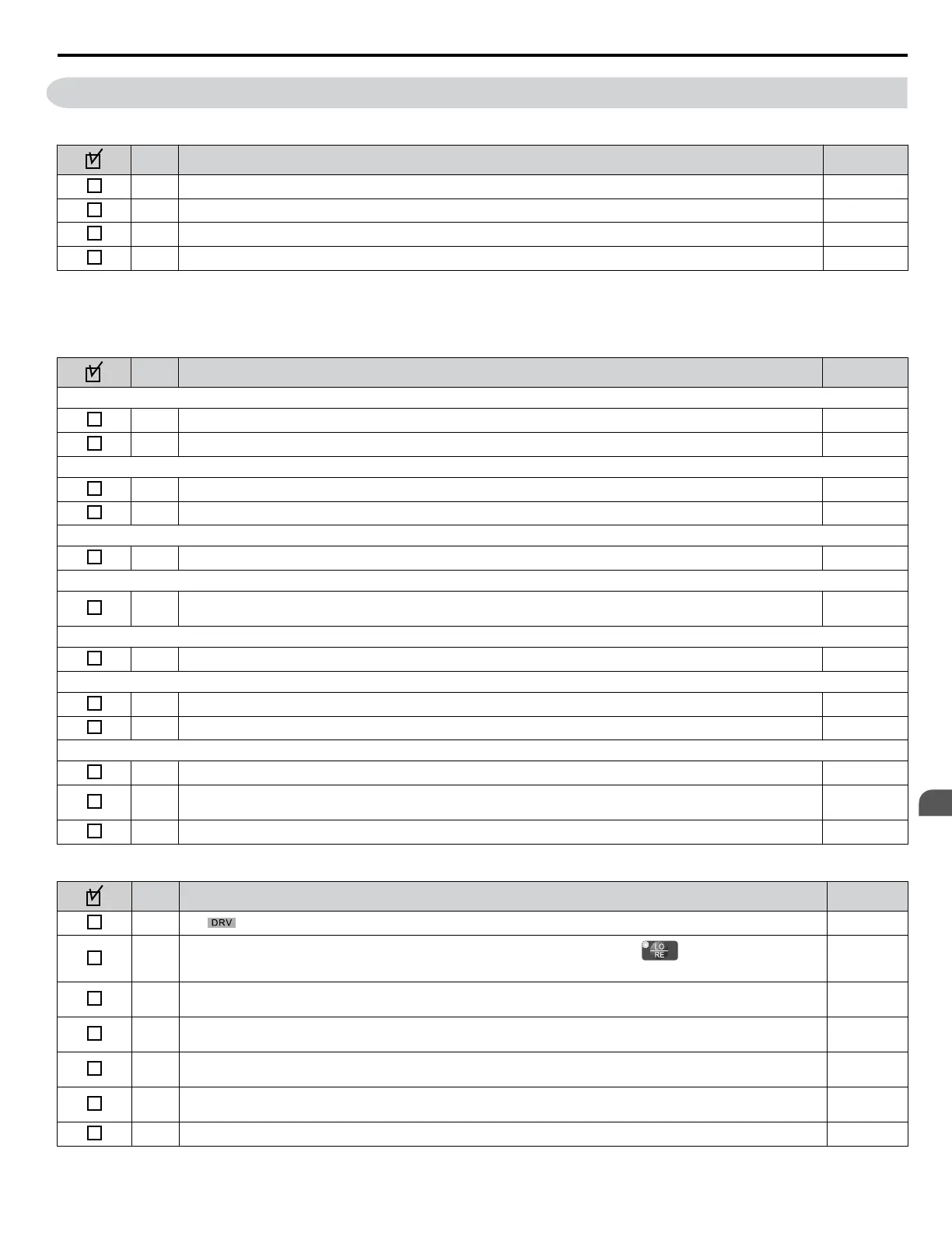
No. Checklist Page
1 Thoroughly read the manual before performing a test run. –
2 Turn the power on. 96
3 Set the voltage for the power supply to E1-01. 184
4 Select the correct duty rating (C6-01) for the application. –
Check the items that correspond to the control mode being used.
WARNING! Sudden Movement Hazard. Ensure start/stop and safety circuits are wired properly and in the correct state before energizing
the drive. Failure to comply could result in death or serious injury from moving equipment. When programmed for 3-Wire control, a momentary
closure on terminal S1 may cause the drive to start.
No.
Checklist Page
V/f Control (A1-02 = 0) and V/f Control with PG (A1-02 = 1)
5 Select the best V/f pattern according to the application and motor characteristics. –
6 Perform Rotational Auto-Tuning for V/f Control if using Energy Saving functions. 100
V/f Control with PG (A1-02 = 1)
7 Set up the PG feedback parameters correctly and make sure the encoder pulse counting direction is correct. 196
8 Set the proportional gain for ASR speed control to C5-01 and the integral time to C5-02. 163
Open Loop Vector Control (A1-02 = 2) or Closed Loop Vector Control (A1-02=3)
9 Perform Auto-Tuning as described. 106
Closed Loop Vector Control (A1-02 = 3)
10
Set the proportional gain for ASR speed control to C5-01 and the integral time to C5-02. Perform ASR Tuning if
possible.
163
Open Loop Vector Control for PM (A1-02 = 5)
11 Perform Auto-Tuning as described. 108
Advanced Open Loop Vector Control for PM (A1-02 = 6)
12 Perform Auto-Tuning as described. 108
13 Set the proportional gain for ASR speed control to C5-01 and the integral time to C5-02. 163
Closed Loop Vector Control for PM (A1-02 = 7)
14 Perform Auto-Tuning as described. 108
15
Set the proportional gain for ASR speed control to C5-01 and the integral time to C5-02. Perform ASR Tuning if
possible.
163
16 Set the encoder Z Pulse offset in parameter E5-11. 108
Proceed to the following checklist after checking items 5 through 16.
No.
Checklist Page
17 The should light after giving a Run command. –
18
To give a Run command and frequency reference from the digital operator, press to set to LOCAL.
The LO/RE key will light.
89
20
If the motor rotates in the opposite direction during the test run, switch two of the drive output terminals
(U/T1, V/T2, W/T3) or change parameter b1-14.
96
21
Set the correct values for the motor rated current (E2-01, E4-01, E5-03) and motor protection (L1-01) to ensure
motor thermal protection.
–
22
If the Run command and frequency reference are provided via the control circuit terminals, set the drive for REMOTE
and be sure the LO/RE light is out.
89
23
If the control circuit terminals should supply the frequency reference, select the correct voltage input signal level (0
to 10 V) or the correct current input signal level (4 to 20 mA or 0 to 20 mA).
126
24 Set the proper voltage to terminal A1 and A3 (-10 to +10 V). 126
4.11 Test Run Checklist
YASKAWA ELECTRIC SIEP C710616 31B YASKAWA AC Drive – A1000 Technical Manual
117
4
Start-Up Programming
& Operation

 Loading...


