n
b8-06: Search Operation Voltage Limit (V/f, V/f w/PG)
Sets the voltage limit for the Speed Search optimal output voltage detection as a percentage of the maximum output voltage.
The drive will keep the output voltage above this level during the search operation to prevent motor stalling.
Note: If set too low, the motor may stall when the load is suddenly increased. Disabled when set to 0. Setting this value to 0 does not disable Energy
Saving.
No. Name Setting Range Default
b8-06 Search Operation Voltage Limit 0 to 100% 0%
u
b9: Zero Servo
The Zero Servo function is a position loop that can be used in CLV and CLV/PM control modes to lock the motor at a certain
position.
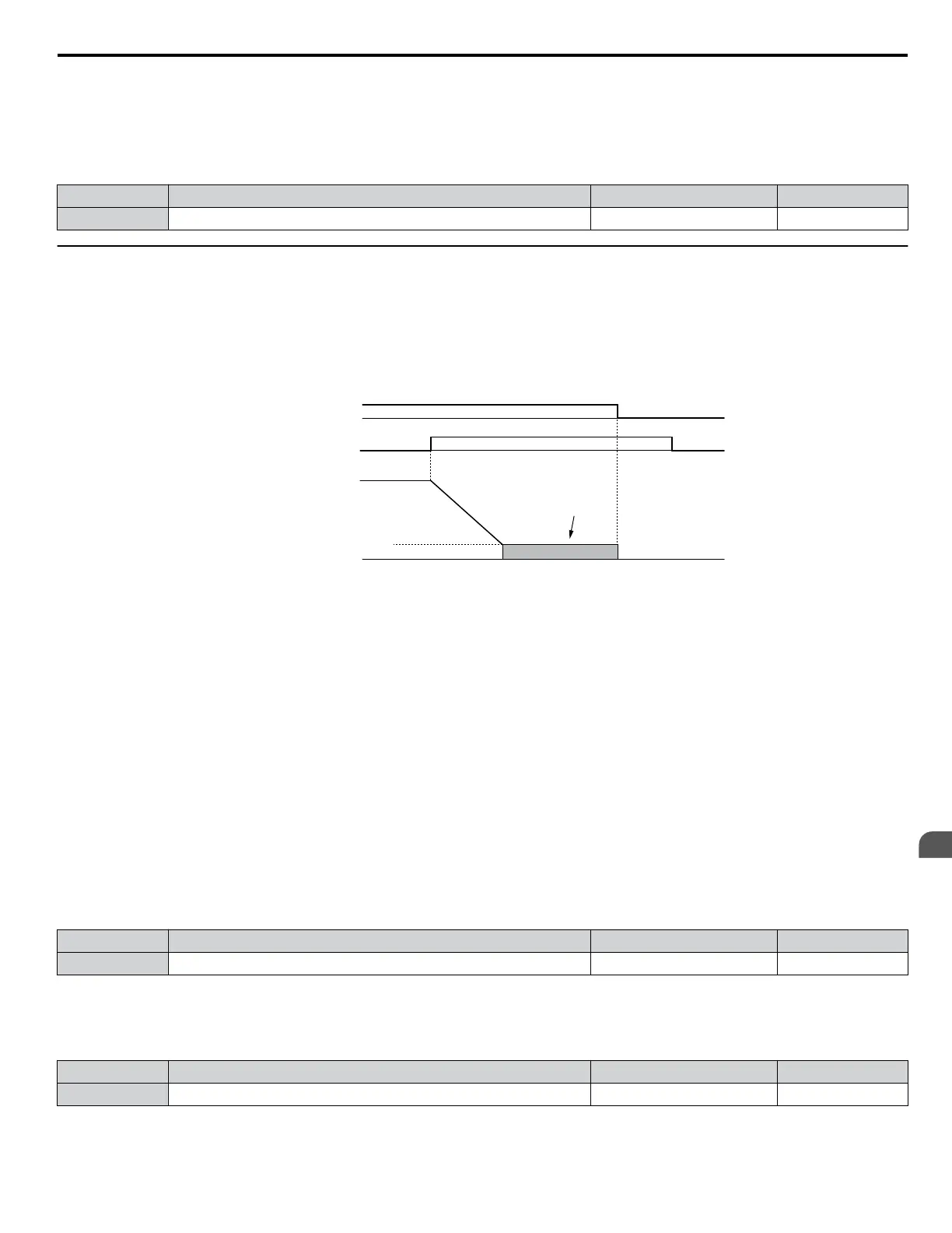
To activate Zero Servo mode, use a digital input set for H1-oo = 72 and the drive will decelerate when this input is closed.
The drive goes into Zero Servo mode and holds the current position when the motor speed falls below the level set to parameter
b2-01. The drive accelerates when the input assigned to trigger the Zero Servo function is released and the Run command is
still present.
ON
ON OFF
OFF
Run command
Zero Servo command
Motor Speed
Zero Servo
Operation
b2-01
DC Injection Braking
start frequency
Figure 5.28 Zero Servo Operation
When Zero Servo mode is active, the deviation between the rotor position and the zero position is displayed in monitor U6-22
(monitor value must be divided by 4 to get the deviation in actual encoder pulses).
A digital output programmed for “Zero Servo complete” (H2-oo = 72) is turned on when the rotor position is within the zero
position, plus or minus the Zero Servo completion width set to parameter b9-02.
Note: 1. The Run command must remain on when using the Zero Servo function. Zero Servo will not hold the load in place if the Run command is
switched off.
2. When the Zero Servo command has shut off, the Zero Servo Completion digital output width also shuts off.
3. Avoid using Zero Servo to lock 100% load for long periods, as this can trigger a fault. If such loads need to be held in place for long periods,
either make sure the current is less than 50% of the drive rated current during Zero Servo, or use a larger capacity drive.
4. If the load rotates the motor when using CLV/PM, a dv4 fault may occur. To prevent this, either increase the Zero Servo gain (b9-01) or
increase the number of pulses set to F1-19 that are required to trigger dv4.
n
b9-01: Zero Servo Gain
Adjusts the responsiveness of the Zero Servo position loop. Increase the value if the response is too slow and the deviation
from the zero position rises too high when load is applied. Decrease the value if vibrations occur during Zero Servo operation.
Note:
Before adjusting the Zero Servo gain, make sure the ASR parameters (C5-oo) are set up properly and vibration or hunting does not occur
when running with a zero speed reference.
No. Name Setting Range Default
b9-01 Zero Servo Gain 0 to 100 5
n
b9-02: Zero Servo Completion Width
Sets the range around zero position within that the Zero Servo complete output signal (H2-oo = 72) is switched on during
Zero Servo operation. The value in b9-02 must be set to the allowable deviation in actual encoder pulses multiplied by four.
No. Name Setting Range Default
b9-02 Zero Servo Completion Width 0 to 16383 10
5.2 b: Application
YASKAWA ELECTRIC SIEP C710616 31B YASKAWA AC Drive – A1000 Technical Manual
153
5
Parameter Details

 Loading...


