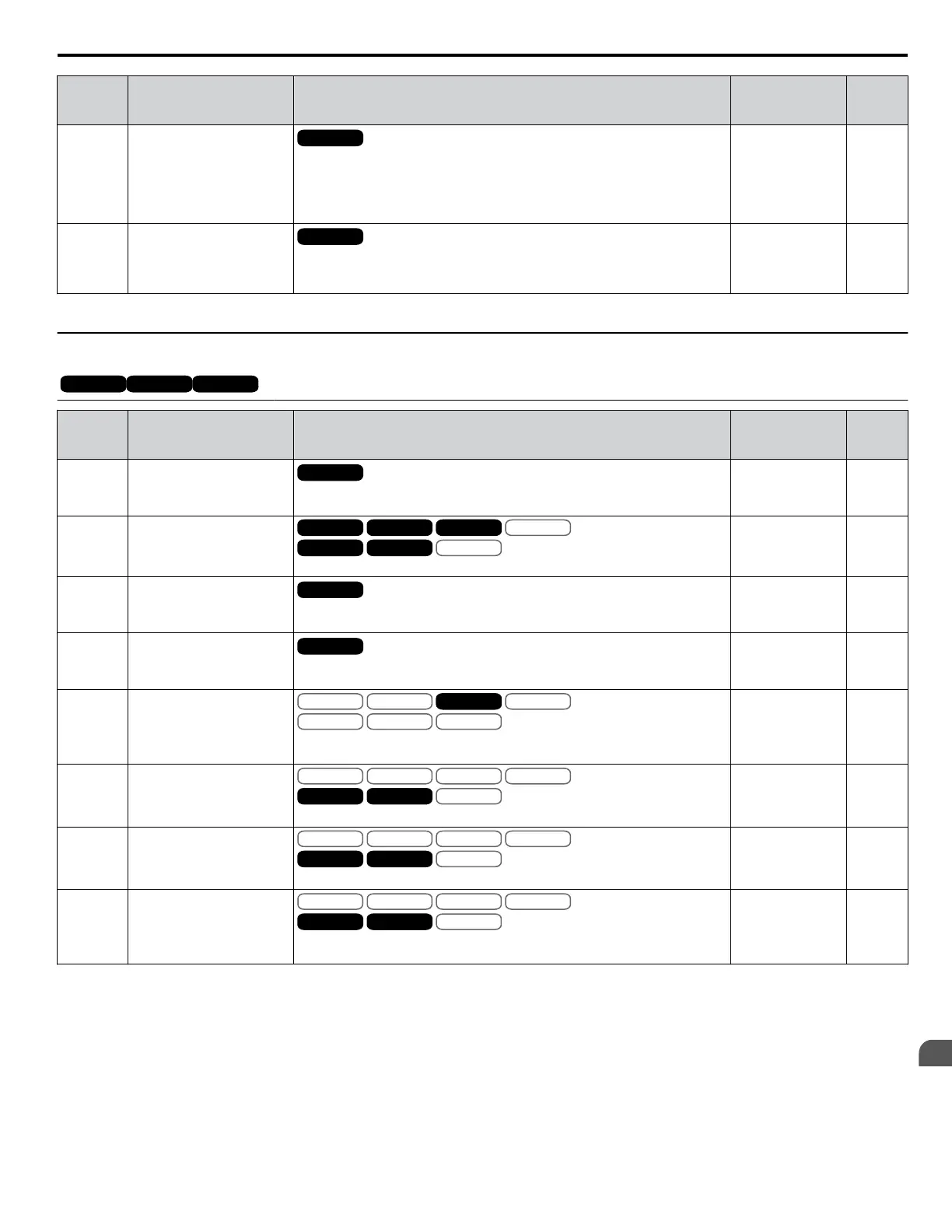
No.
(Addr.
Hex)
Name Description Values Page
b1-16
(1C5)
Run Command
Selection 2
All Modes
Enabled when a terminal set for “External reference” (H1-oo = 2) closes.
0: Digital operator
1: Digital input terminals
2: MEMOBUS/Modbus communications
3: Option card
Default: 0
Range: 0 to 3
133
b1-17
(1C6)
Run Command at Power Up
All Modes
0: Disregarded. A new Run command must be issued after power up.
1: Allowed. Motor will start immediately after power up if a Run command
is already enabled.
Default: 0
Range: 0, 1
133
<1> Settings 2 and 3 are not available in CLV.
u
b2: DC Injection Braking and Short Circuit Braking
OLV/PMOLV/PM AOLV/PMAOLV/PM CLV/PMCLV/PM
PM motor control modes are not available on 600 V class drives, CIMR-Ao5oooooooo.
No.
(Addr.
Hex)
Name Description Values Page
b2-01
(189)
DC Injection Braking Start
Frequency
All Modes
Sets the frequency at which DC Injection Braking starts when “Ramp to stop”
(b1-03 = 0) is selected.
Default:
<1>
Min.: 0.0 Hz
Max.: 10.0 Hz
133
b2-02
(18A)
DC Injection Braking
Current
V/f
OLV/PM
V/f w PG
AOLV/PM
OLV
CLV/PM
CLV
Sets the DC Injection Braking current as a percentage of the drive rated current.
Default: 50%
Min.: 0
Max.: 100
134
b2-03
(18B)
DC Injection Braking Time
at Start
All Modes
Sets DC Injection Braking (Zero Speed Control when in CLV and CLV/PM)
time at start. Disabled when set to 0.00 seconds.
Default: 0.00 s
Min.: 0.00
Max.: 10.00
134
b2-04
(18C)
DC Injection Braking Time
at Stop
All Modes
Sets DC Injection Braking (Zero Speed Control when in CLV and CLV/PM)
time at stop.
Default:
<1>
Min.: 0.00 s
Max.: 10.00 s
134
b2-08
(190)
Magnetic Flux
Compensation Value
V/f
OLV/PM
V/f w PG
AOLV/PM
OLV
CLV/PM
CLV
Sets the magnetic flux compensation as a percentage of the no-load current
value (E2-03).
Default: 0%
Min.: 0
Max.: 1000
134
b2-12
(1BA)
Short Circuit Brake Time at
Start
V/f
OLV/PM
V/f w PG
AOLV/PM
OLV
CLV/PM
CLV
Sets the time for Short Circuit Braking operation at start.
<2>
Default: 0.00 s
Min.: 0.00
Max.: 25.50
135
b2-13
(1BB)
Short Circuit Brake Time at
Stop
V/f
OLV/PM
V/f w PG
AOLV/PM
OLV
CLV/PM
CLV
Sets the Short Circuit Braking operation time at stop.
<2>
Default: 0.50 s
Min.: 0.00
Max.: 25.50
135
b2-18
(177)
Short Circuit Braking
Current
V/f
OLV/PM
V/f w PG
AOLV/PM
OLV
CLV/PM
CLV
Determines the current level for Short Circuit Braking. Set as a percentage of
the motor rated current.
Default: 100.0%
Min.: 0.0
Max.: 200.0
135
<1> Default setting is determined by parameter A1-02, Control Mode Setting.
<2> A coasting motor may require a braking resistor circuit to bring the motor to a stop in the required time.
B.4 b: Application
YASKAWA ELECTRIC SIEP C710616 31B YASKAWA AC Drive – A1000 Technical Manual
385
B
Parameter List

 Loading...


