Setting 2: BCD, 0.01% units
Setting 3: BCD, 1 Hz units
Setting 4: BCD, 0.1 Hz units
Setting 5: BCD, 0.01 Hz units
Setting 6: BCD, special setting (5 digit input), 0.02 Hz units
Setting 7: Binary
n
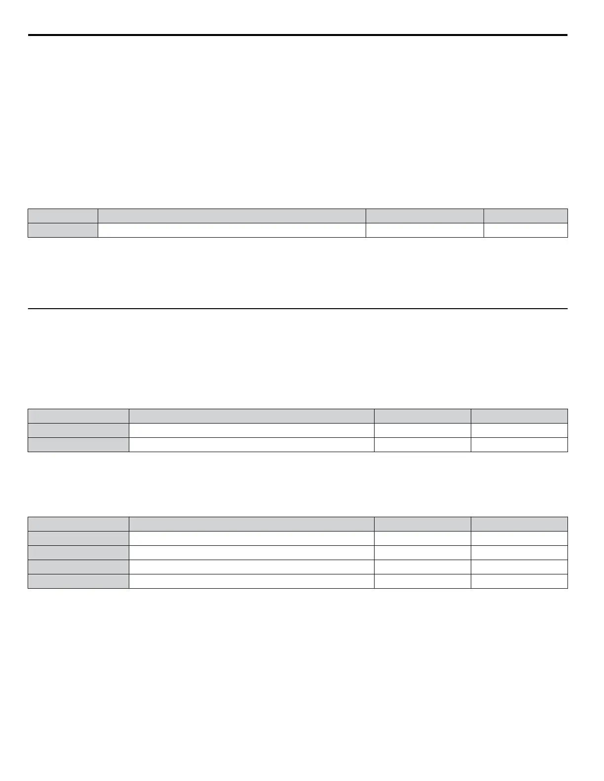
F3-03: Digital Input Option DI-A3 Data Length Selection
Determines the number of bits for the option card input that sets the frequency reference.
No. Parameter Name Setting Range Default
F3-03 Digital Input Option DI-A3 Data Length Selection 0 to 2 2
Setting 0: 8 bit
Setting 1: 12 bit
Setting 2: 16 bit
u
F4: Analog Monitor Card Settings
These parameters set the drive for operation with the analog output option card AO-A3. Refer to the instruction manual
packaged with the option card for specific details on installation, wiring, input signal level selection, and parameter setup.
n
F4-01, F4-03: Terminal V1, V2 Monitor Selection
Selects the data to output from analog terminal V1. Enter the final three digits of Uo-ooto determine which monitor data
is output from the option card. Some monitors are only available in certain control modes.
No. Parameter Name Setting Range Default
F4-01 Terminal V1 Monitor Selection 000 to 999 102
F4-03 Terminal V2 Monitor Selection 000 to 999 103
n
F4-02, F4-04, F4-05, F4-06: Terminal V1, V2 Monitor Gain and Bias
Parameters F4-02 and F4-04 determine the gain, while parameters F4-05 and F4-06 set the bias. These parameters are set as
a percentage of the output signal from V1 and V2 where 100% equals 10 V output. The terminal output voltage is limited to
10 V.
No. Parameter Name Setting Range Default
F4-02 Terminal V1 Monitor Gain -999.9 to 999.9% 100.0%
F4-04 Terminal V2 Monitor Gain -999.9 to 999.9% 50.0%
F4-05 Terminal V1 Monitor Bias -999.9 to 999.9% 0.0%
F4-06 Terminal V2 Monitor Bias -999.9 to 999.9% 0.0%
Using Gain and Bias to Adjust Output Signal Level
When viewing the values set to F4-02 or F4-05 on the digital operator, a voltage equal to 100% of the parameter being viewed
(including current gain and bias settings) will be output from terminal V1 or V2. When viewing the value set to F4-05 or
F4-06, terminal V1 or V2 will output a voltage equal to 0% of the parameter being viewed (including current gain and bias
settings).
Example 1: F4-02 = 0%, F4-02 = 80%. When the parameter setting display for F4-02 is accessed using the digital operator,
terminal V1 will output a voltage of 8 V, even when the drive is stopped.
Example 2: F4-03 = 5%. When the parameter setting display for F4-03 is accessed using the digital operator, terminal V1 will
output a voltage of 0.5 V, even when the drive is stopped.
5.6 F: Option Settings
200
YASKAWA ELECTRIC SIEP C710616 31B YASKAWA AC Drive – A1000 Technical Manual

 Loading...


