Manual Parameter Setup
Calculate parameter L3-25 in the formula below:
L3-25 =
Machine Inertia
Motor Inertia
n
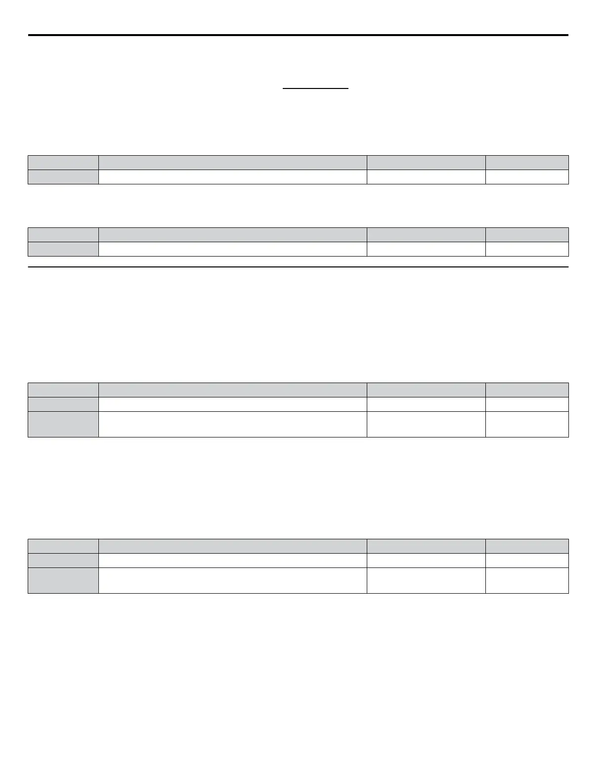
L3-26: Additional DC Bus Capacitors
Sets the capacity of any additionally installed DC bus capacitors. This data is used in calculations for Single Drive KEB Ride-
Thru 2. Adjust this setting only if external capacity is connected to the DC bus and Single Drive KEB 2 is used.
No. Name Setting Range Default
L3-26 Additional DC Bus Capacitors 0 to 65000 μF 0 μF
n
L3-27: Stall Prevention Detection Time
Sets a delay time from when the Stall Prevention level is reached and the actual Stall Prevention function is activated.
No. Name Setting Range Default
L3-27 Stall Prevention Detection Time 0 to 5000 ms 50 ms
u
L4: Speed Detection
These parameters set up the speed agree and speed detection functions that can be assigned to the multi-function output
terminals.
n
L4-01, L4-02: Speed Agreement Detection Level and Detection Width
Parameter L4-01 sets the detection level for the digital output functions “Speed agree 1,” “User-set speed agree 1,” “Frequency
detection 1,” and “Frequency detection 2.”
Parameter L4-02 sets the hysteresis level for these functions.
No. Name Setting Range Default
L4-01 Speed Agreement Detection Level 0.0 to 400.0 Hz 0.0 Hz
L4-02 Speed Agreement Detection Width
0.0 to 20.0 Hz
0.0 to 40.0%
<1>
Determined by
A1-02
<1> Setting units in Hz when A1-02 = 0, 1, 2, 3, or 5. Setting units in % when A1-02 = 6 or 7.
Refer to H2-01 to H2-03: Terminal M1-M2, M3-M4, and M5-M6 Function Selection on page 218, Settings 2, 3, 4, and 5.
n
L4-03, L4-04: Speed Agreement Detection Level and Detection Width (+/-)
Parameter L4-03 sets the detection level for the digital output functions “Speed agree 2,” “User-set speed agree 2,” “Frequency
detection 3,” and “Frequency detection 4.”
Parameter L4-04 sets the hysteresis level for these functions.
No. Name Setting Range Default
L4-03 Speed Agreement Detection Level (+/-) -400.0 to 400.0 Hz 0.0 Hz
L4-04 Speed Agreement Detection Width (+/-)
0.0 to 20.0 Hz
0.0 to 40.0%
<1>
Determined by
A1-02
<1> Setting units in Hz when A1-02 = 0, 1, 2, 3, or 5. Setting units in % when A1-02 = 6 or 7.
Refer to H2-01 to H2-03: Terminal M1-M2, M3-M4, and M5-M6 Function Selection on page 218, Settings 13, 14, 15, and
16.
5.8 L: Protection Functions
256
YASKAWA ELECTRIC SIEP C710616 31B YASKAWA AC Drive – A1000 Technical Manual

 Loading...


