n
Speed Estimation Type Speed Search (b3-24 = 1)
This method can be used for a single induction motor connected to a drive. Do not use this method if the motor is one or more
frame size smaller than the drive, at motor speeds above 200 Hz, or when using a single drive to operate more than one motor.
Speed Estimation is executed in the two steps described below:
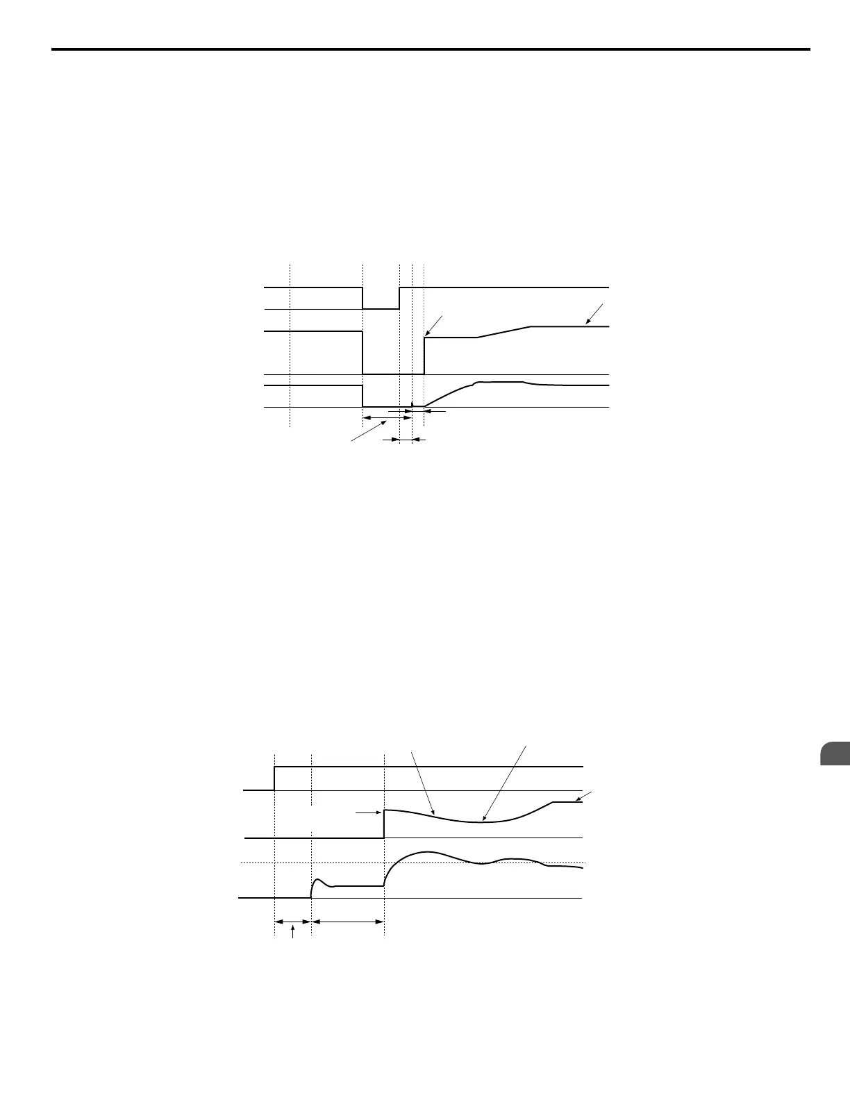
Step 1: Back EMF Voltage Estimation
This method is used by Speed Search after baseblock (e.g., a power loss where the drive CPU continued to run and the Run
command was kept active). Here, the drive estimates the motor speed by analyzing the back EMF voltage and outputs the
estimated frequency and increases the voltage using the time constant set in parameter L2-04. After that, the motor is accelerated
or decelerated to the frequency reference starting from the detected speed. If there is not enough residual voltage in the motor
windings to perform the calculations described above, the drive will automatically proceed to step 2.
AC power
supply
Output
frequency
Output
current
OFFON
Starts at the speed
that was detected
Selected
frequency
reference
Min. Baseblock Time
(L2-03)
Several miliseconds
b3 -05
<1>
Figure 5.18 Speed Search after Baseblock
<1> After AC power is restored, the drive will wait for at least the time set to b3-05. If the power interruption is longer than
the minimum baseblock time set to L2-03, the drive will wait until the time set to b3-05 has passed after power is restored
before starting Speed Search.
Step 2: Current Injection
Current Injection is performed when there is insufficient residual voltage in the motor after extended power losses, when Speed
Search is applied with the Run command (b3-01 = 1), or when an External search command is used.
This feature injects the amount of DC current set to b3-06 to the motor and detects the speed by measuring the current feedback.
The drive then outputs the detected frequency and increases the voltage using the time constant set to parameter L2-04 while
looking at the motor current.
The output frequency is reduced if the current is higher than the level in b3-02. When the current falls below b3-02, the motor
speed is assumed to be found and the drive starts to accelerate or decelerate to the frequency reference.
Run command
Output
frequency
Output
current
OFF
ON
b3-02
Starts at the speed
speed that was detected
Waits twice as long as L2-04
Frequency reference
set to the drive
Decelerates at the Speed
Search decel time set to b3-03
1.0 s
Min. Baseblock Time (L2-03) <1>
Figure 5.19 Speed Search at Start
<1> The wait time for Speed Search (b3-05) determines the lower limit.
5.2 b: Application
YASKAWA ELECTRIC SIEP C710616 31B YASKAWA AC Drive – A1000 Technical Manual
137
5
Parameter Details

 Loading...


