Some option cards come with several different lead lines for connecting the card to the drive. Select the lead line with
the most appropriate length.
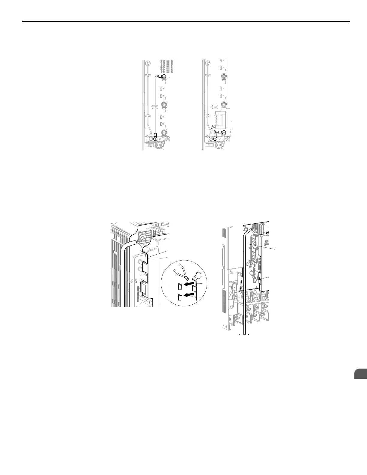
Note: There are only two screw holes on the drive for ground terminals. When connecting three option cards, two lead lines will need
to share the same ground terminal.
Figure 8.3 Connecting the Ground Terminal
4.
Wire the option card to the terminal block on the option card.
Refer to the option card manual for wiring instructions.
When installing option cards to models CIMR-Ao5A0003 to 0011, it may be necessary to route the cables connected
to the option through the top cover to the outside. In this case, cut out the perforated openings on the left side of the
drive top cover, being careful not to leave any sharp edges that may damage the cable.
Models CIMR-Ao5A0017 to 0032 have enough space to keep all wiring inside the unit.
A
B
A – Cable through hole
(CIMR-Ao5A00033 to 0011)
B – Space for wiring
(CIMR-Ao5A0017 to 0032)
Figure 8.4 Wiring Space
5.
Replace the front cover and digital operator on the drive.
Note: 1. Leave enough space when wiring to easily reattach the front cover. Make sure no wires get caught between the front cover
and the drive.
2. Any exposed wiring will void the wall-mount enclosure rating.
8.4 Option Card Installation
YASKAWA ELECTRIC SIEP C710616 31B YASKAWA AC Drive – A1000 Technical Manual
365
8
Peripheral Devices &
Options

 Loading...


