10 s
etc.
time
10 s 10 s 10 s 10 s 10 s 10 s
f
ref
× (L8-19)
f
ref
× (L8-19)
2
f
ref
× (L8-19)
4
f
ref
× (L8-19)
3
f
ref
Output frequency
Reset oH
Alarm
Reset oH
Alarm
Digital ouput (4D)
oH
Alarm
oH
Alarm
oH
Alarm
oH
Alarm
oH alarm number
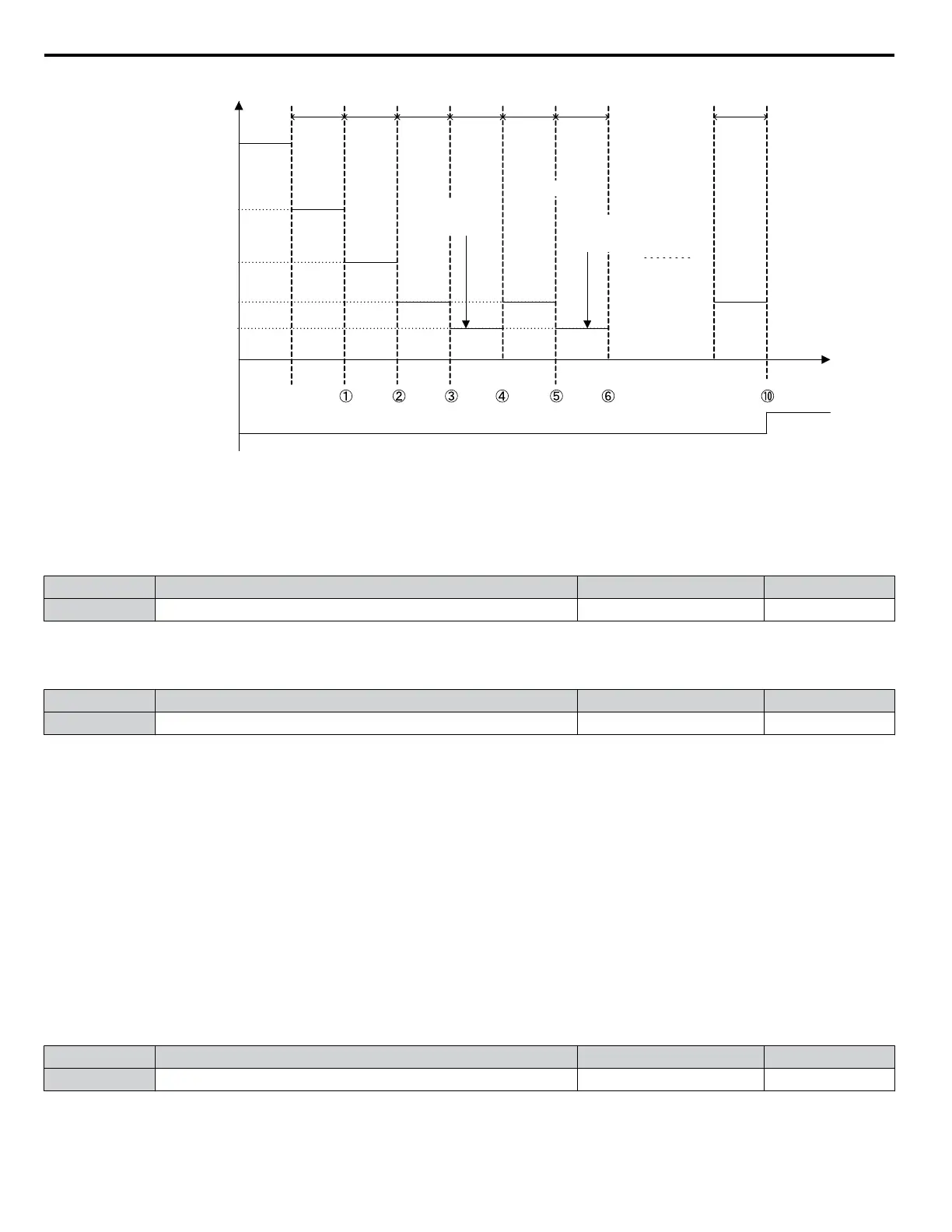
Figure 5.104 Output Frequency Reduction During Overheat Alarm
n
L8-19: Frequency Reduction Rate during Overheat Pre-Alarm
Specifies the output frequency reduction when L8-03 is set to 4 and an oH alarm is present. Set as a factor of the maximum
output frequency.
No. Name Setting Range Default
L8-19 Frequency Reduction Rate During Overheat Pre-Alarm 0.1 to 0.9 0.8
n
L8-05: Input Phase Loss Protection Selection
Enables or disables the input phase loss detection.
No. Name Setting Range Default
L8-05 Input Phase Loss Protection Selection 0, 1 1
Setting 0: Disabled
Setting 1: Enabled
Enables input phase loss detection. Since measuring the DC bus ripple detects input phase loss, a power supply voltage
imbalance or main circuit capacitor deterioration may also trigger a phase loss fault (PF).
Detection is disabled if:
• The drive is decelerating.
• No Run command is active.
• Output current is less than or equal to 30% of the drive rated current.
n
L8-07: Output Phase Loss Protection Selection
Enables or disables the output phase loss detection triggered when the output current falls below 5% of the drive rated current.
Note: 1. Output phase loss detection can mistakenly be triggered if the motor rated current is very small compared to the drive rating. Disable this
parameter in such cases.
2. Output phase loss detection is not possible when the drive is running a PM motor with light load.
No. Name Setting Range Default
L8-07 Output Phase Loss Protection Selection 0 to 2 0
Setting 0: Disabled
5.8 L: Protection Functions
264
YASKAWA ELECTRIC SIEP C710616 31B YASKAWA AC Drive – A1000 Technical Manual

 Loading...


