n
b5-35: PID Input Limit
Sets the maximum allowed PID input as a percentage of the maximum output frequency (E1-04). Parameter b5-35 acts as a
bipolar limit.
No. Name Setting Range Default
b5-35 PID Input Limit 0 to 1000.0% 1000.0%
n
b5-38, b5-39: PID Setpoint User Display, PID Setpoint Display Digits
When parameter b5-20 is set to 3, parameters b5-38 and b5-39 set a user-defined display for the PID setpoint (b5-19) and PID
feedback monitors (U5-01, U5-04).
Parameter b5-38 determines the display value when the maximum frequency is output and parameter b5-39 determines the
number of digits. The setting value is equal to the number of decimal places.
No. Name Setting Range Default
b5-38 PID Setpoint User Display 1 to 60000
Determined by
b5-20
b5-39 PID Setpoint Display Digits 0 to 3
Determined by
b5-20
n
b5-40: Frequency Reference Monitor Content During PID
Sets the content of the frequency reference monitor display (U1-01) when PID control is active.
No. Name Setting Range Default
b5-40 Frequency Reference Monitor Content During PID 0, 1 0
Setting 0: Frequency Reference after PID
Monitor U1-01 displays the frequency reference increased or reduced for the PID output.
Setting 1: Frequency Reference
Monitor U1-01 displays the frequency reference value.
n
Fine-Tuning PID
Follow the directions below to fine tune PID control parameters:
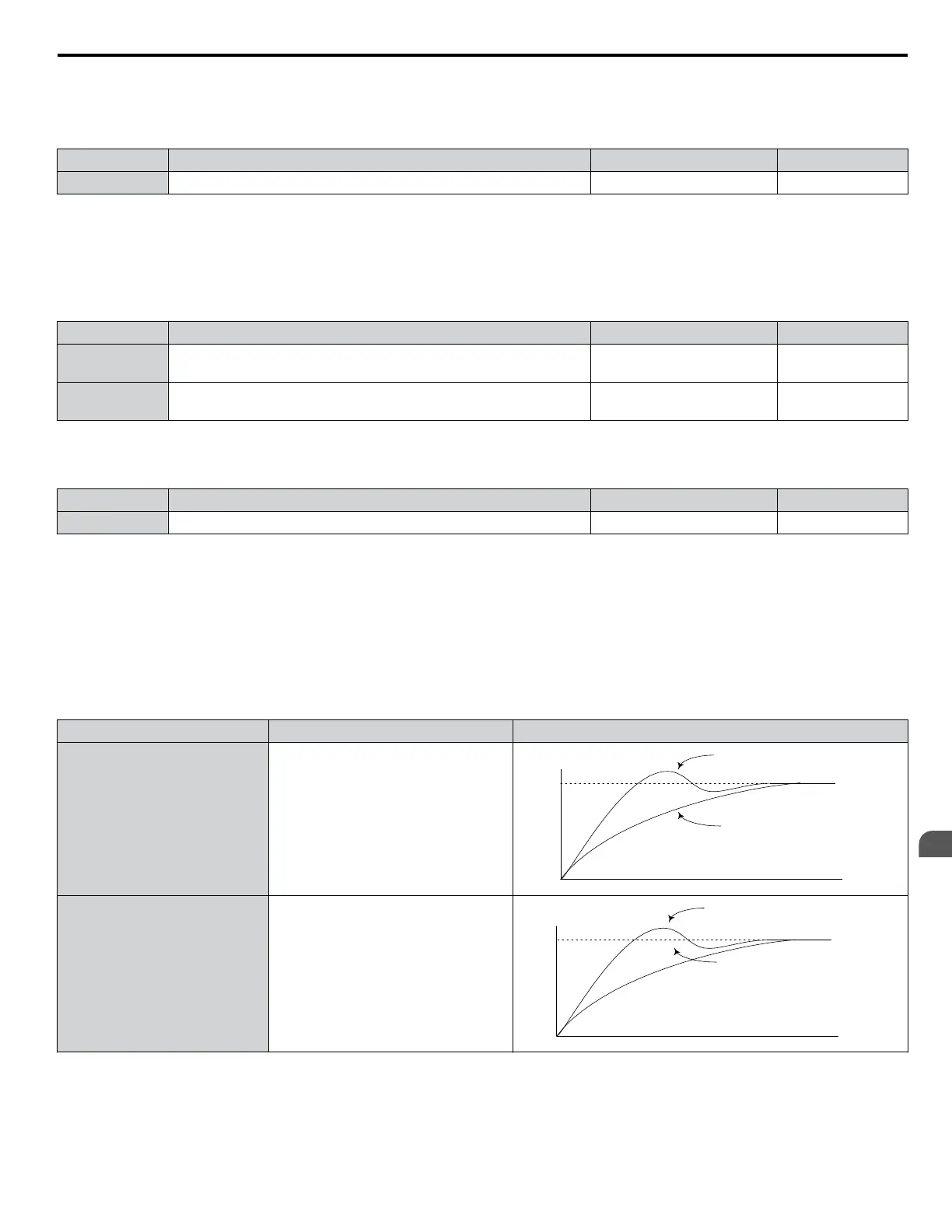
Table 5.11 PID Fine Tuning
Goal Tuning Procedure Result
Suppress overshoot
• Reduce the derivative time (b5-05)
• Increase the integral time (b5-03)
Response
Before adjustment
After adjustment
Time
Achieve stability quickly while
allowing some overshoot
• Decrease the integral time (b5-03)
• Increase the derivative time (b5-05)
Response
Before adjustment
After adjustment
Time
5.2 b: Application
YASKAWA ELECTRIC SIEP C710616 31B YASKAWA AC Drive – A1000 Technical Manual
149
5
Parameter Details

 Loading...


