Motor has overheated.
• Check the load size, accel/decel times, and cycle times.
• Decrease the load.
• Increase accel and decel times (C1-01 to C1-08).
• Adjust the preset V/f pattern (E1-04 through E1-10). This will mainly involve reducing E1-08 and E1-10.
Note: Do not lower E1-08 and E1-10 excessively, because this reduces load tolerance at low speeds.
• Check the motor-rated current.
• Enter motor-rated current on motor nameplate (E2-01).
• Ensure the motor cooling system is operating normally.
• Repair or replace the motor cooling system.
Digital Operator Display Minor Fault Name
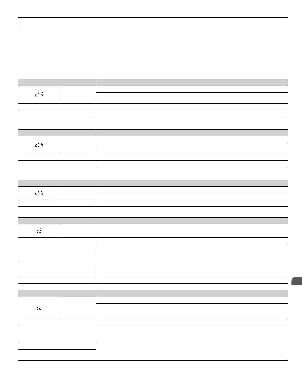
oL3
Overtorque 1
Drive output current (or torque in OLV, CLV, AOLV/PM, CLV/PM) was greater than L6-02 for longer than
the time set in L6-03.
Cause Possible Solutions
Inappropriate parameter settings. Check parameters L6-02 and L6-03.
There is a fault on the machine side (e.g.,
the machine is locked up).
• Check the status of the machine.
• Remove the cause of the fault.
Digital Operator Display Minor Fault Name
oL4
Overtorque 2
Drive output current (or torque in OLV, CLV, AOLV/PM, CLV/PM) was greater than L6-05 for longer than
the time set in L6-06.
Cause Possible Solutions
Parameter settings are not appropriate. Check parameters L6-05 and L6-06.
There is a fault on the machine side (e.g.,
the machine is locked up).
• Check the status of the machine being used.
• Remove the cause of the fault.
Digital Operator Display Minor Fault Name
oL5
Mechanical Weakening Detection 1
Overtorque occurred, matching the conditions specified in L6-08.
Cause Possible Solutions
Overtorque occurred, triggering the
mechanical weakening level set to L6-08.
Check for the cause of mechanical weakening.
Digital Operator Display Minor Fault Name
oS
Overspeed (for Control Mode with PG)
The motor speed feedback exceeded the F1-08 setting.
Cause Possible Solutions
Overshoot is occurring.
• Increase the settings for C5-01 (Speed Control Proportional Gain 1) and reduce C5-02 (Speed Control
Integral Time 1).
• If using a Closed Loop Vector mode enable Feed Forward Control and perform Inertia Auto-Tuning.
Incorrect speed feedback scaling if terminal
RP is used as speed feedback input in V/f
control
• Set H6-02 to value of the speed feedback signal frequency when the motor runs at the maximum speed.
• Adjust the input signal using parameters H6-03 through H6-05.
Incorrect PG pulse number has been set • Check and correct parameter F1-01.
Inappropriate parameter settings. Check the setting for the overspeed detection level and the overspeed detection time (F1-08 and F1-09).
Digital Operator Display Minor Fault Name
ov
DC Bus Overvoltage
The DC bus voltage exceeded the trip point.
Refer to the Overvoltage Protection row in the A.3 Drive Specifications section on page 374 for trip level
values.
Cause Possible Solutions
Surge voltage present in the drive input
power.
• Install a DC reactor or an AC reactor.
• Voltage surge can result from a thyristor convertor and a phase advancing capacitor operating on the same
drive input power system.
The motor is short-circuited.
• Check the motor power cable, relay terminals and motor terminal box for short circuits.
• Correct grounding shorts and turn the power back on.
Ground current has over-charged the main
circuit capacitors via the drive input power.
6.5 Alarm Detection
YASKAWA ELECTRIC SIEP C710616 31B YASKAWA AC Drive – A1000 Technical Manual
321
6
Troubleshooting

 Loading...


