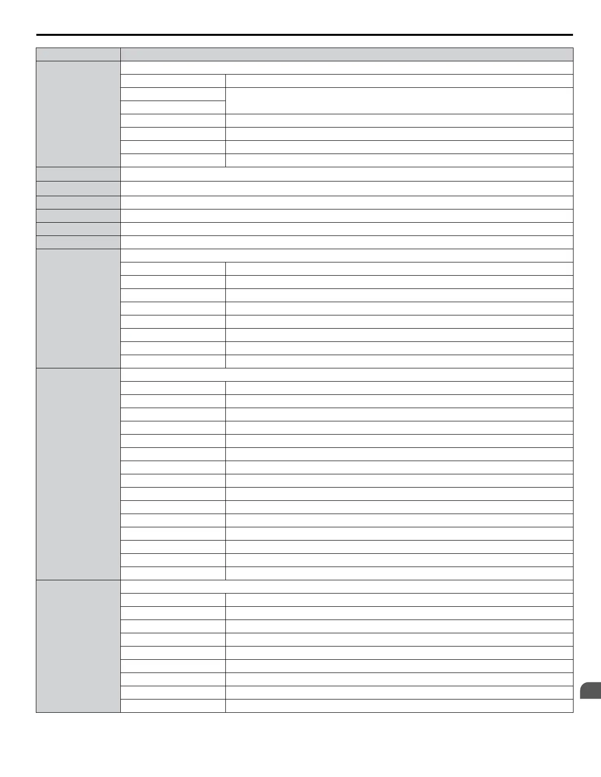
Register No. Contents
0022H
Data Link Status
bit 0 Writing data or switching motors
bit 1
Reserved
bit 2
bit 3 Upper or lower limit error
bit 4 Data conformity error
bit 5 Writing to EEPROM
bit 6 to bit F Reserved
0023H
Frequency Reference
<1>
0024H
Output Frequency
<1>
0025H Output Voltage Reference, 0.1 V units (units are determined by parameter H5-10)
0026H Output Current, 0.1 A units
0027H Output Power
0028H Torque Reference
0029H
Fault Contents 2
bit 0 Reserved
bit 1 Ground Fault (GF)
bit 2 Input Phase Loss (PF)
bit 3 Output Phase Loss (LF)
bit 4 Braking Resistor Overheat (rH)
bit 5 Reserved
bit 6 Motor Overheat 2 (PTC input) (oH4)
bit 7 to bit F Reserved
002AH
Alarm Contents1
bit 0, 1 Reserved
bit 2 Run Command Input Error (EF)
bit 3 Drive Baseblock (bb)
bit 4 Overtorque Detection 1 (oL3)
bit 5 Heatsink Overheat (oH)
bit 6 Overvoltage (ov)
bit 7 Undervoltage (Uv)
bit 8 Cooling Fan Error (FAn)
bit 9 MEMOBUS/Modbus Communication Error (CE)
bit A Option Communication Error (bUS)
bit B Undertorque Detection 1/2 (UL3/UL4)
bit C Motor Overheat (oH3)
bit D PID Feedback Loss (FbL, FbH)
bit E Reserved
bit F Serial Communication Transmission Error (CALL)
002BH
Input Terminal Status
bit 0 Terminal S1 Closed
bit 1 Terminal S2 Closed
bit 2 Terminal S3 Closed
bit 3 Terminal S4 Closed
bit 4 Terminal S5 Closed
bit 5 Terminal S6 Closed
bit 6 Terminal S7 Closed
bit 7 Terminal S8 Closed
bit 8 to bit F Reserved
C.9 MEMOBUS/Modbus Data Table
YASKAWA ELECTRIC SIEP C710616 31B YASKAWA AC Drive – A1000 Technical Manual
479
C
MEMOBUS/Modbus
Communications

 Loading...


