12 Modification of System Configuration
12.2Allocating External I/O Signal
12-4
182582-1CD
182582-1CD
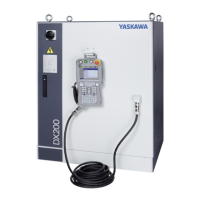
MH900, DX200 Controller
12.2 Allocating External I/O Signal
Allocation of the external I/O signal
The DX200 exchanges I/O data with the I/O interface by using external I/O
signal area (#2xxxxm #3xxxx). The allocation of the external-I/O signal
area and I/O interface used to be unchangeable since they have been
allocated to the signals from lower to higher numbers in bytes (8 points
unit) by system software.
With the function of allocating the external-I/O signal, the change is
possible and a user can specify the signals in byte (8 points unit) to
allocate.
1. The EXTERNAL IO SETUP window appears.
#0xxxx
#1xxxx
#2xxxx
#3xxxx
#4xxxx
#5xxxx
I/O Interface
I/O process in the DX200 (outline)
GPIO board
JANCD-YI021-E
Optional IO board
e.g., CC-Link
e.g., DeviceNet
External I/O
signal allocation
External I/O
signal area
Concurrent I/O
ladder program
GPIO signal area
Specific I/O
signal area
Other signal/
register area

 Loading...


