14-12
182582-1CD
182582-1CD
14 Description of Units and Circuit Boards
14.5Machine Safety I/O Logic Circuit Board (JANCD-YSF22ჱ-E)
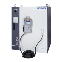
MH900, DX200 Controller
14.5.2 Connection for Tool Shock Sensor (SHOCK)
14.5.2.1 To Connect the Tool Shock Sensor Directly to the Tool Shock Sensor
Signal Line
1. Disconnect the minus SHOCK (-) and +24V2 pin terminal from the
DINAMIC connector, the machine safety I/O logic circuit board
(YSF22 ჱ -CN215). The pin terminal for the shock sensor is attached
on the right side of the controller.
2. Connect the minus SHOCK (-) and +24V2 pin terminals to the signal
line of the tool shock sensor. Use the following pin terminals for
preparing the end of the signal line.
Fig. 14-8: Direct Connection to Tool Shock Sensor Signal Line
Pin Terminal Name Pin Terminal Model Signal Line Terminal Model
SHOCK- TMEDN-630809-MA TMEDN-630809-FA
(manufactured by NICHIFU Co.,
Ltd.)
+24V2 TMEDN-630809-FA TMEDN-630809-MA
(manufactured by NICHIFU Co.,
Ltd.)
A3
B3
CN215
SHOCK-
DX200
SHOCK+
SHOCK-
TMEDN-630809-MA (NICHIFU)
TMEDN-630809-FA (NICHIFU)
+24V2
Machine safety I/O logic
circuit board
TMEDN-630809-MA (NICHIFU)
TMEDN-630809-FA (NICHIFU)
Shock sensor
(Option)
Manipulator
Shock sensor signal cable
The pin terminal for the shock sensor is
attached on the right side of the controller.

 Loading...


