www.dadehpardazan.ir 88594014-15
1 Outline
1.4.1 Single-phase 100 V, SGDV-R70F05A, -R90F05A, -2R1F05A Models
1-8
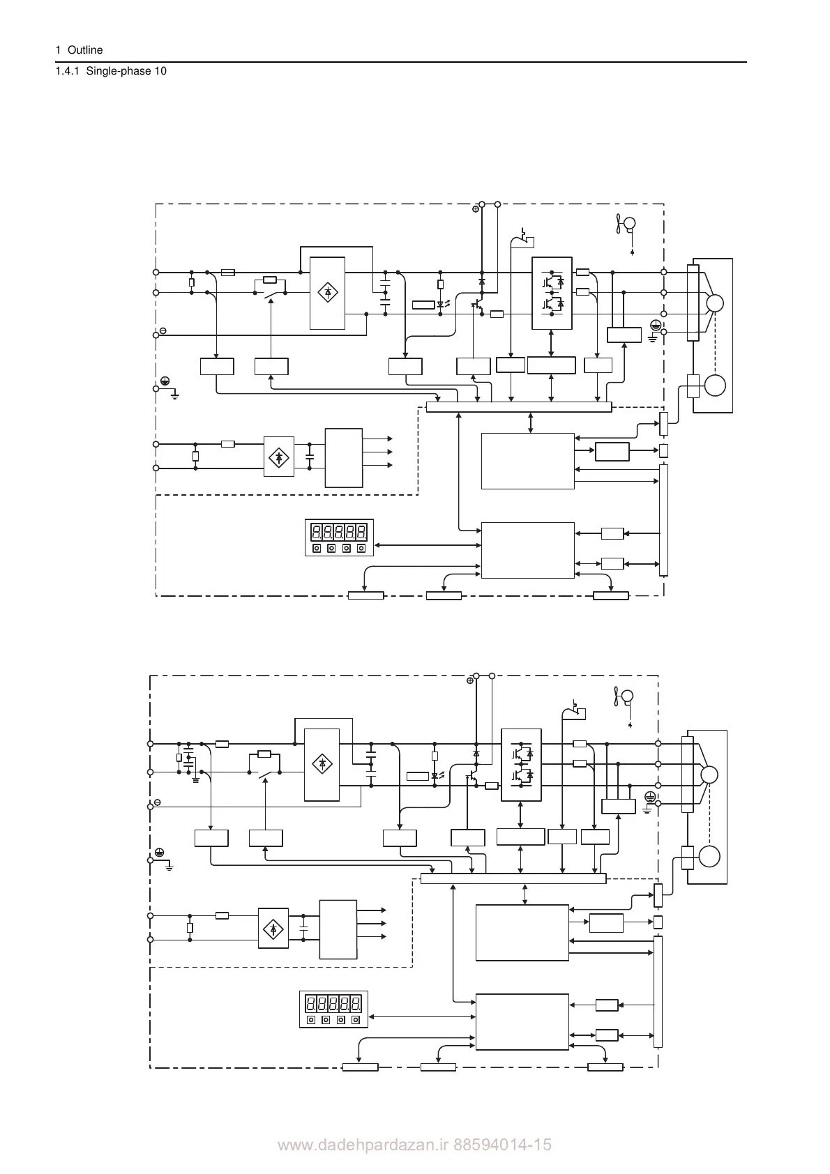
1.4 SERVOPACK Internal Block Diagrams
1.4.1 Single-phase 100 V, SGDV-R70F05A, -R90F05A, -2R1F05A Models
1.4.2 Si
ngle-phase 100 V, SGDV-2R8F05A Model
L1
B1/ B2
L2
L1C
L2C
U
V
W
CHARGE
M
ENC
CN3
CN2
A/D
I/O
CN1
CN5
CN7 CN8
Control power
supply
Main circuit
power supply
Control
power
supply
±12 V
+5 V
+17 V
Current
sensor
Dynamic
brake circuit
Servomotor
Gate
drive
Voltage
sensor
Voltage
sensor
Varistor
Varistor
Gate drive
overcurrent
protector
Temperature
sensor
Relay
drive
+
12 V
Fan
ASIC
(PWM control, etc.)
CPU
(Position/speed
calculation, etc.)
Panel operator
Digital operator
Analog monitor
output
Reference pulse
input
Reference voltage input
I/O signal
Analog
voltage
converter
Personal
computer
Signal for safety function
Encoder output pulse
+
–
+
–
+
–
L1
L2
L1C
L2C
B1/ B2
U
V
W
CHARGE
M
ENC
CN3
CN2
A/D
I/O
CN1
CN5
CN7 CN8
+12 V
±12 V
+5 V
+17 V
Control
power
supply
Current
sensor
Dynamic
brake circuit
Servomotor
Gate
drive
Voltage
sensor
Voltage
sensor
Varistor
Varistor
Gate drive
overcurrent
protector
Temperature
sensor
Relay
drive
Fan
ASIC
(PWM control, etc.)
CPU
(Position/speed
calculation, etc.)
Panel operator
Digital operator
Analog monitor
output
Reference pulse
input
Reference valtage input
I/O signal
Analog
voltage
converter
Personal
computer
Signal for safety function
+
–
+
–
+
–
Control power
supply
Main circuit
power supply
Encoder output pulse