www.dadehpardazan.ir 88594014-15
3 Wiring and Connection
3.4.1 Reference Input Circuit
3-30
3.4 Examples of Connection to Host Controller
This section shows examples of SERVOPACK I/O signal connection to the host controller.
3.4.1 Reference Input Circuit
(1) Analog Input Circuit
CN1 connector terminals, 5-6 (speed reference input) and 9-10 (force reference input) are explained below.
Analog signals are either speed or force reference
signals at the impedance below.
• Reference speed input: Approx. 14 k
• Reference force input: Approx. 14 k
The maximum allowable voltages for in
put signals is ±12 V.
This wiring example is for forward operation.
(2) Position Reference Input Circuit
CN1 connector terminals, 7-8 (reference pulse input), 11-12 (reference sign input) and 14-15 (clear input) are
explained below. The output circuits for the reference pulse and position error clear signal from the host con-
troller can be either a line-driver output or open-col
lector output. The position reference input circuits are
shown below by output type.
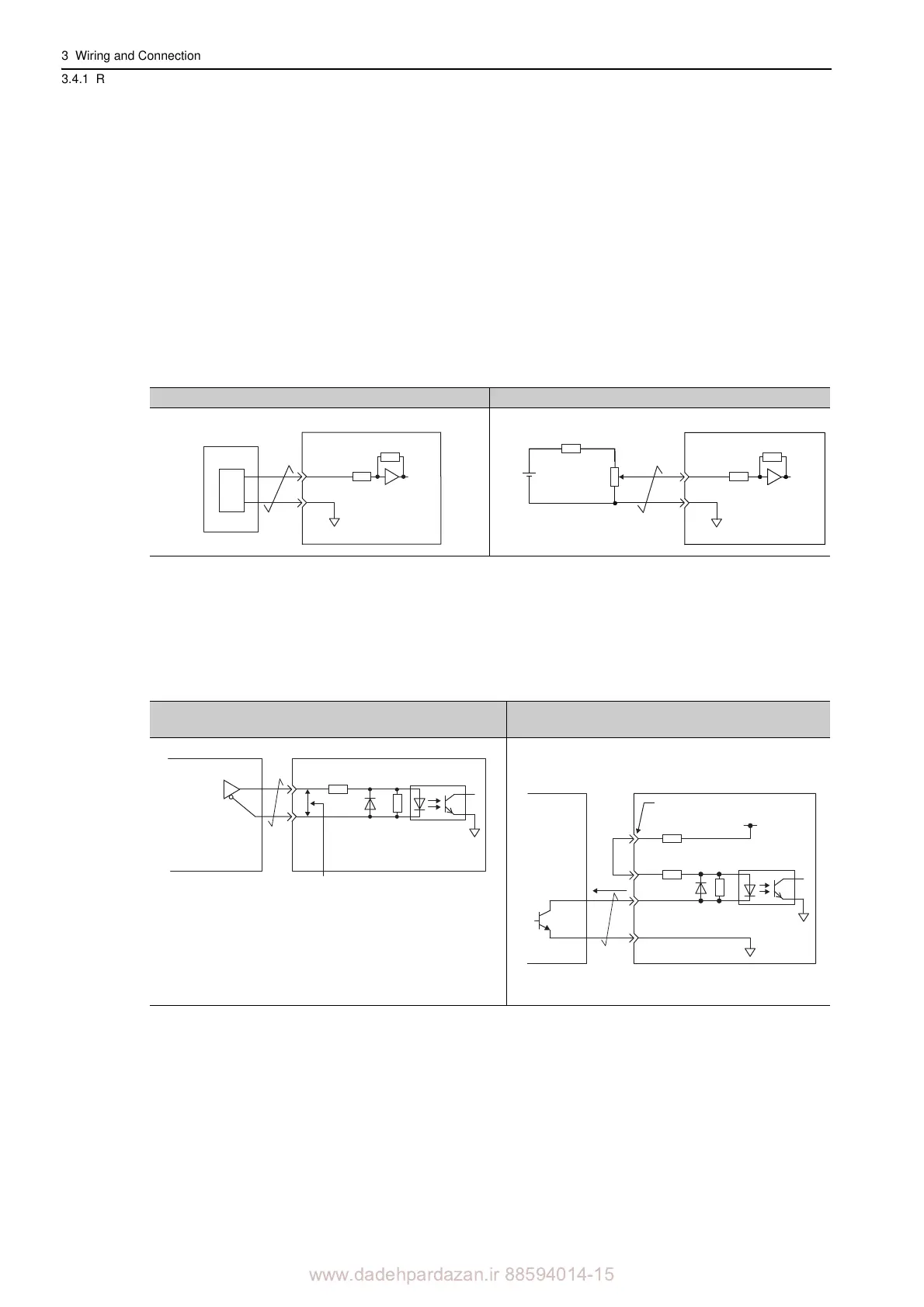
Analog Voltage Input Circuit (D/A) Analog Voltage Input Circuit (Wiring Example)*
Host controller
0 V
SG
Approx.14 kΩ min.
SERVOPACK
V-REF or
T-REF
D/A
25HP-10B
2 kΩ
Approx.14 kΩ min.
1.8 kΩ (1/2 W) min.
12 V
0 V
SG
SERVOPACK
V-REF or
T-REF
Line-driver Output Circuit
Open-collector Output
(Built-in 12-V power supply)
2.8 V ≤ (H level) − (L level) ≤ 3.7 V
Applicable line
driver:
SN75ALS174
manufactured by
Texas Instruments
or the equivalent
If the above formula is not satisfied,
the inputs to the SERVOPACK will be
unstable. Pulses may be missed from
the reference pulse input, reference
inversion may occur for the reference
sign input, and the clear signal may
be OFF for the clear input.
150 Ω
4.7 kΩ
Host controller
SERVOPACK
1.5 V or
less at ON
SERVOPACK
Host Controller
PL1, PL2, or PL3 terminal
0 V
+12 V
4.7 kΩ
150 Ω
Approx. 9 mA