www.dadehpardazan.ir 88594014-15
5 Operation
5-36
5.4 Position Control
This section describes operation with position control.
Select position control with Pn000.1.
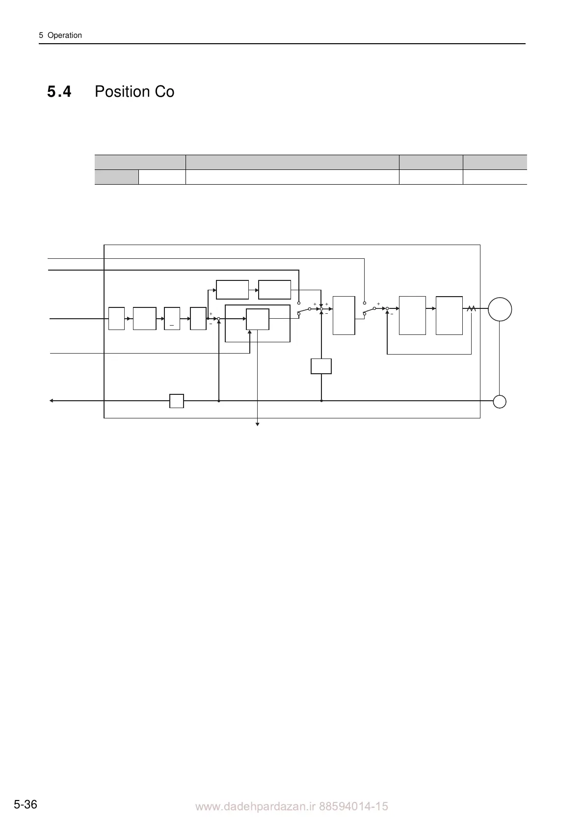
Block Diagram for Position Control
A block diagram for position control is shown below.
The reference pulse input multiplication switching function is supported by software version 001A or later.
Parameter Meaning When Enabled Classification
Pn000 n.1 Position Control After restart Setup
Pn10A
Error
counter
Position
control section
Position
feedback
Speed feedback
Linear
scale
Current feedback
Force reference
Speed reference
Clear signal input
Position reference
ENC
M
Power
amplifier
Divider
Speed
conversion
Pn000.1 Pn000.1
Pn200.0 Pn218
Pn109
Pn20E
Pn210
COIN
Pn281
Pn216
Pn217
Encoder
output pulse
SERVOPACK
Servomotor
Feed-
forward
Elec-
tronic
gear
Reference
Pulse
Multiplier
× n
Smooth-
ing
Feedforward
filter time
constant
Pn522
Positioning
completed
width
Speed
control
section
Current
control
section
B
A
*
Refer-
ence
pulse
form