www.dadehpardazan.ir 88594014-15
3 Wiring and Connection
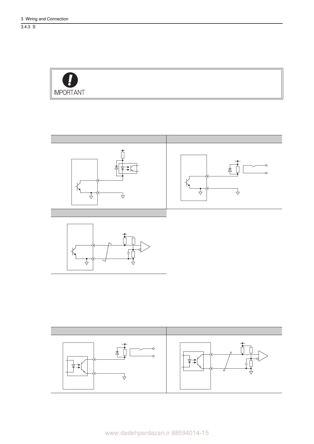
3.4.3 Sequence Output Circuit
3-34
3.4.3 Sequence Output Circuit
Four types of SERVOPACK output circuit are available.
(1) Open-collector Output Circuit
CN1 connector terminals 37 to 39 (alarm code output) are explained below.
Alarm code signals (ALO1, ALO2, ALO3) are output from open
-collector transistor output circuits. Connect
an open-collector output circuit through a photocoupler, relay or line receiver circuit.
Note: The maximum allowable voltage and maximum current capacity for open-collector output circuits are as follows.
• Voltage: 30 VDC
• Current: 20 mA DC
(2) Photocoupler Output Circuit
Photocoupler output circuits are used for servo alarm (ALM), servo ready (/S-RDY), and other sequence out-
put signal circuits. Connect a photocoupler output circuit through a
relay or line receiver circuit.
Note: The maximum allowable voltage and the allowable range of current capacity for photocoupler output circuits are as
follows.
• Voltage: 30 VDC
• Current: 5 to 50 mA DC
Incorrect wiring or incorrect voltage application to
the output circuit may cause short-cir-
cuit.
If a short-circuit occurs as a result of any
of these causes, the holding brake will not
work. This could damage the machine or cause an accident resulting in death or injury.
Photocoupler Circuit Example Relay Circuit Example
Line Receiver Circuit Example
0V
0V
SERVOPACK
5 to 12 VDC
Photocoupler
0V
Relay
5 to 24 VDC
SERVOPACK
0V
SERVOPACK
5 to 12 VDC
Relay Circuit Example Line Receiver Circuit Example
0V
Relay
5 to 24 VDC
SERVOPACK