www.dadehpardazan.ir 88594014-15
4 Trial Operation
4.3.2 Trial Operation in Speed Control
4-6
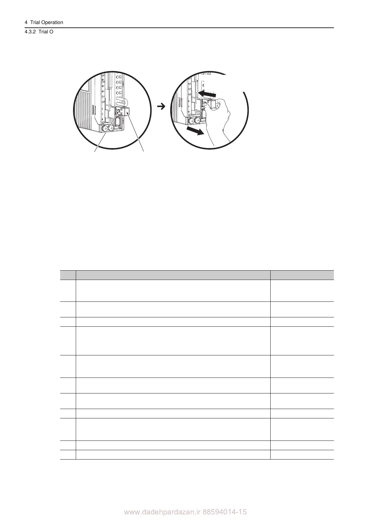
2. Slide the lock injector of the safety function’s jumper connector to the SERVOPACK side to
unlock and remove the safety function’s jumper connector.
Note: The safety function jumper connector may be damaged if removed while the lock is still on.
3. Connect a safety function device to CN8.
Note: When not using the safety function, use the SERVOPACK with the safety function’s jumper connector (JZSP-
CVH05-E provided as an accessory) inserted in CN8. If the SERVOPACK is used without the jumper connector
inserted into CN8, no current will flow to the servomotor and no force will be output. In this case, "Hbb" will be dis-
played on the panel operator or the digital operator.
4.3.2 Trial Operation in Speed Control
Perform the following steps for trial operation in speed control. The steps are specified on the condition that
input signal wiring for the speed control has been completed according to 4.3.1 Inspecting Connection and
Status of Input Signals.
Lock injector
Safety function’s
jumper connector
1. Slide the lock injector
to the SERVOPACK
side.
Enlarged View
Remove the safety function’s
jumper connector while the lock
injector is slid to the SERVOPACK
side.
2.
Step Operation Reference
1
Recheck the power supply and the input signal circuits, and turn ON the SERVO-
PACK control power supply.
3.2.3 Example of I/O Sig-
nal Connections in Speed
Control
2 Adjust the speed reference input gain (Pn300).
5.3.1 Basic Settings for
Speed Control
3 Turn ON the main circuit power supply of the SERVOPACK.
4
Check that speed reference input (the voltage between
V-REF and SG) is 0 V, and
turn ON the servo ON (/S-ON) input signal.
Note: If the servomotor moves at a very low speed with the sp
eed reference input at
0 V, adjust the reference offset so that the servomotor will not move.
5.3.2 Reference Offset
Adjustment
5
Gradually increase the voltage of the speed ref
erence input (i.e., the voltage between
V-REF and SG) from 0 V.
Note: The factory setting is 6
V at the rated speed.
5.3.1 Basic Settings for
Speed Control
6 Check the speed reference value using the
monitor display (Un001).
8.1 List of Monitor Dis-
plays
7 Check the motor moving speed using the
monitor display (Un000).
8.1 List of Monitor Dis-
plays
8 Check that the values in step 6 and step 7 (Un001 and Un000) are equal to each other.
9
Check the motor movement direction.
Note: To switch the motor movement direction without changing the p
olarity of the
analog speed reference, refer to 5.2.3 Servomotor Movement Direction
5.2.3 Servomotor Move-
ment Direction
10 Return the speed reference input to 0 V.
11 Turn OFF the servo ON signal (/S-ON).