www.dadehpardazan.ir 88594014-15
3.1 Main Circuit Wiring
3-3
Do not short-circuit between B1/ and B2. It may damage the SERVOPACK.
The DC reactor connection terminals are short-circuited when the SERVOPACK is shipped from the factory: 1 and
2.
3.1.2 Using a Standard Power Supply
(Single-phase 100 V, Three-phase 200 V
, or Three-phase 400 V)
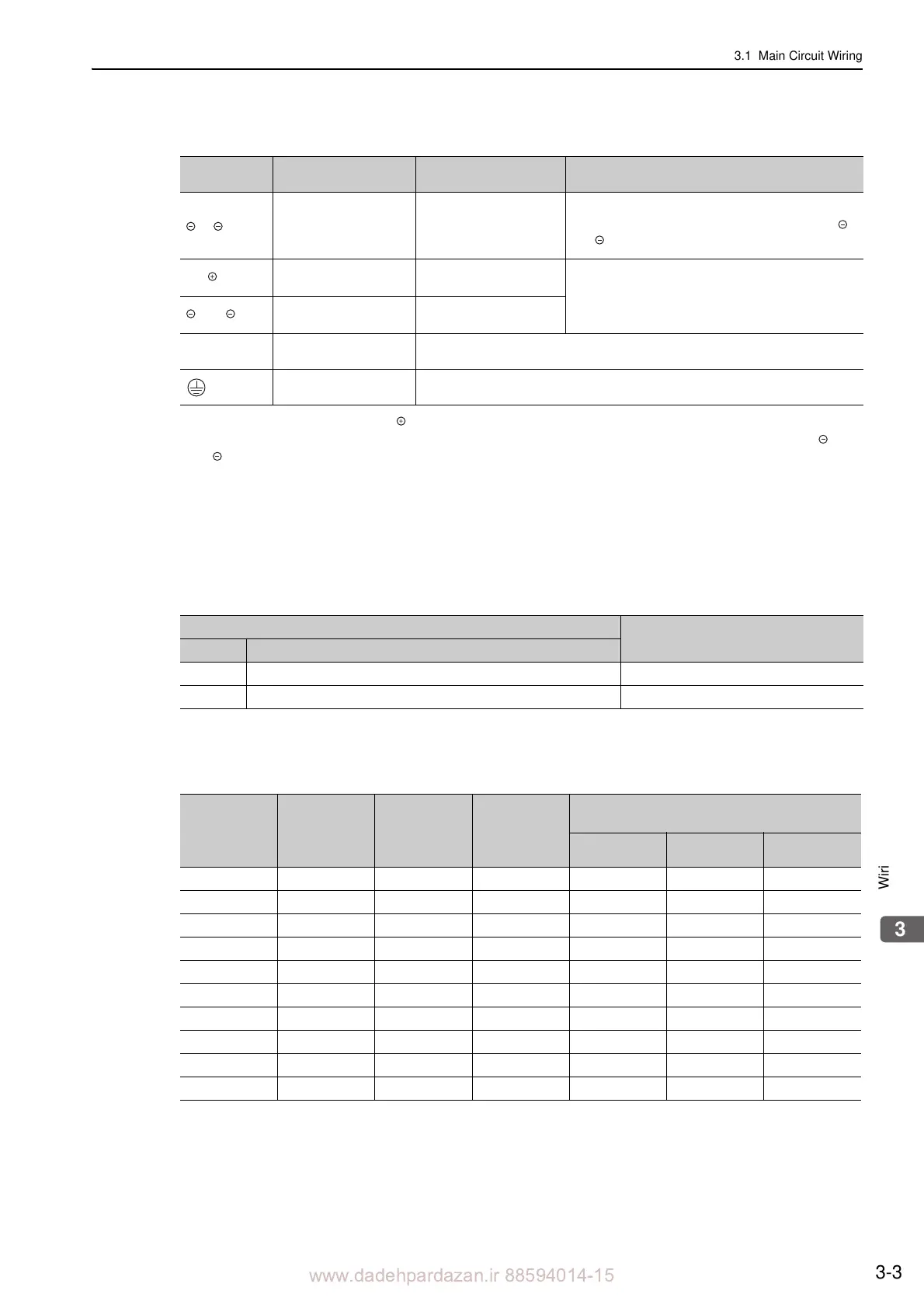
(1) Wire Types
Use the following type of wire for main circuit.
The following table shows the wire sizes and allowable cur
rents for three wires. Use wires with specifications
equal to or less than those shown in the table.
•
600 V grade heat-resistant polyvinyl chloride insulated wire (HIV)
Note: The values in the table are for reference only.
1, 2
*2
DC reactor connec-
tion terminal for pow-
er supply harmonic
suppression
A
D
If a countermeasure against power supply harmonic
waves is needed, connect a DC reactor between 1
and 2.
B1/
Main circuit positive
terminal
A
D
Use when DC power supply input is used.
2 or
Main circuit negative
terminal
A
D
U, V, W
Servomotor connec-
tion terminals
Use for connecting to the servomotor.
Ground terminals
(2)
Use for connecting the power supply ground
terminal and servomotor ground
terminal.
(cont’d)
Terminal
Symbols
Name Model SGDV-
Specification
Cable Type
Allowable Conductor Temperature C
Symbol Name
IV 600 V grade polyvinyl chloride insulated wire 60
HIV 600 V grade heat-resistant polyvinyl chloride insulated wire 75
AWG Size
Nominal
Cross Sec-
tion Area
(mm
2
)
Configuration
(Number of
Wires/mm
2
)
Conductive
Resistance
(/km)
Allowable Current at Surrounding Air Temper-
ature (A)
30C 40C 50C
20 0.5 19/0.18 39.5 6.6 5.6 4.5
19 0.75 30/0.18 26.0 8.8 7.0 5.5
18 0.9 37/0.18 24.4 9.0 7.7 6.0
16 1.25 50/0.18 15.6 12.0 11.0 8.5
14 2.0 7/0.6 9.53 23 20 16
12 3.5 7/0.8 5.41 33 29 24
10 5.5 7/1.0 3.47 43 38 31
8 8.0 7/1.2 2.41 55 49 40
6 14.0 7/1.6 1.35 79 70 57
4 22.0 7/2.0 0.85 91 81 66