www.dadehpardazan.ir 88594014-15
5.2 Basic Functions Settings
5-7
5.2.4 Overtravel
The overtravel limit function forces movable machine parts to stop if they exceed the allowable range of
motion and turn ON a limit switch.
(1) Signal Setting
Movement in the opposite direction is possible during overtravel by inputting the reference.
CAUTION
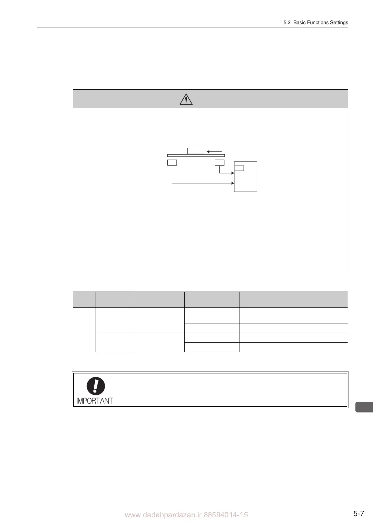
• Installing limit switches
For machines that move using linear motion, connect
limit switches to P-OT and N-OT of CN1 as shown below to
prevent machine damage. To prevent a contact fault or disconnection from causing accidents, make sure that the limit
switches are normally closed.
• Axes to which external force is applied in overtravel
Vertical axes:
Occurrence of overtravel may cause a workpiece to fall, because the /BK signal is on, that is when the brake is
r
eleased. Set the parameter (Pn001 = n.1) to bring the servomotor to zero clamp state after stopping to prevent
a workpiece from falling.
Other axes to which external force is applied:
Overtravel will bring about a baseblock state after
the servomotor stops, which may cause the servomotor to be
pushed back by the load’s external force. To prevent this, set the parameter (Pn001 = n.1) to bring the servo-
motor to zero clamp state after stopping.
For details on how to set the parameter, refer to (3) Servomotor Stopping Method When
Overtravel is Used.
43
CN1
42
P-OT
N-OT
Limit
switch
Servomotor
SERVOPACK
Limit
switch
Forward direction
Type Name
Connector
Pin Number
Setting Meaning
Input
P-OT CN1-42
ON
Forward run allowed.
Normal operation status.
OFF Forward run prohibited. Forward overtravel.
N-OT CN1-43
ON Reverse run allowed. Normal operation
status.
OFF Reverse run prohibited. Reverse overtravel.
When the servomotor stops due to overtravel during position control, the position errors
are held. A clear signal (CLR) input is required to clear the error pulses.
For the clear signal, refer to 5.4.2 Clear Signal Setting.