www.dadehpardazan.ir 88594014-15
3 Wiring and Connection
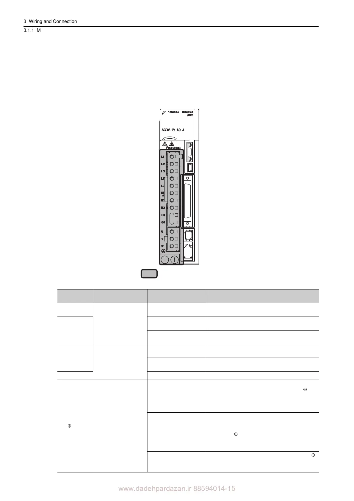
3.1.1 Main Circuit Terminals
3-2
3.1 Main Circuit Wiring
The names and specifications of the main circuit terminals are given below.
Also this section describes the general precautions for wiring
and precautions under special environments.
3.1.1 Main Circuit Terminals
: Main circuit terminals
CN3
CN7
CN1
CN8
CN2
㧢
Terminal
Symbols
Name Model SGDV-
Specification
L1, L2
Main circuit power in-
put terminals
F
Single-phase 100 to 115 V,
+10% to -15% (50/60 Hz)
L1, L2, L3
A
Three-phase 200 to 230 V,
+10% to -15% (50/60 Hz)
D
Three-phase 380 to 480 V,
+10% to -15% (50/60 Hz)
L1C, L2C
Control power input
te
rminals
F
Single-phase 100 to 115 V,
+10% to -15% (50/60 Hz)
A
Single-phase 200 to 230 V,
+10% to -15% (50/60 Hz)
24V, 0V D
24 VDC,
15%
B1/ , B2
*1
External regenera-
tive resistor connec-
tion terminals
R70F, R90F, 2R1F,
2R8F
, R70A, R90A,
1R6A, 2R8A
If the regenerative c
apacity is insufficient, connect
an external regenerative resistor between B1/ and
B2.
Note: The external regenerative resisto
r is not
included.
3R8A, 5R5A, 7R6A,
120A, 180A, 2
00A,
330A, 1R9D, 3R5D,
5R4D, 8R4D, 120D,
170D
If the internal regenerative resistor is
insufficient,
remove the lead or shorting bar between B2 and B3
and connect an external regenerative resistor
between B1/ and B2.
Note: The external regenerative resistor is not
included.
550A, 260D
Connect a regenerative resistor unit
between B1/
and B2.
Note: The regenerative resistor
unit is not included.