www.dadehpardazan.ir 88594014-15
1.4 SERVOPACK Internal Block Diagrams
1-13
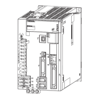
1.4.11 Three-phase 400 V, SGDV-8R4D05A, -120D05A Models
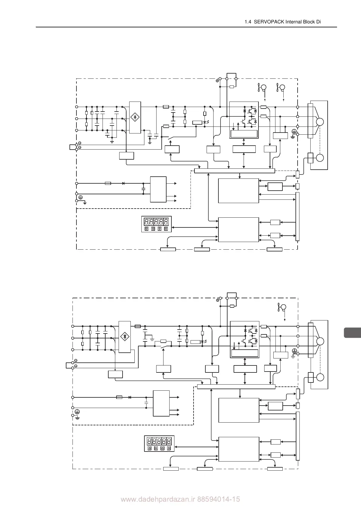
1.4.12 Three-phase 400 V, SGDV-170D05A Model
L1
B1/ B2 B3
L2
L3
1
2
+24 V
0 V
U
V
W
CN3
CN2
ENC
A/D
I/O
CN1
CN5
M
CHARGE
CN7 CN8
+15 V × 4
+5 V
±12 V
+
–
+
–
Current
sensor
Servomotor
Gate
drive
Voltage
sensor
Voltage
sensor
Relay
drive
ASIC
(PWM control, etc.)
CPU
(Position/speed
calculation, etc.)
Panel operator
Digital operator
Analog monitor
output
Reference pulse
input
Reference voltage input
I/O signal
Analog
voltage
converter
Personal
computer
Signal for safety function
Control
power
supply
Overheat protector,
overcurrent protector
Dynamic
brake circuit
Varistor
±12 V ±12 V
Fan 1 Fan 2
+
–
Main circuit
power supply
Control power
supply
Encoder output pulse
(The 24 VDC
power supply is
not included.)
L1
B1/ B2 B3
L2
L3
1
2
+24 V
0 V
U
V
W
CN3
CN2
ENC
A/D
I/O
CN1
CN5
M
CHARGE
CN7 CN8
+15 V × 4
+5 V
±12 V
+
–
+
–
Current
sensor
Servomotor
Gate
drive
Voltage
sensor
Voltage
sensor
Relay
drive
ASIC
(PWM control, etc.)
CPU
(Position/speed
calculation, etc.)
Panel operator
Digital operator
Analog monitor
output
Reference pulse
input
Reference voltage input
I/O signal
Analog
voltage
converter
Personal
computer
Signal for safety function
Control
power
supply
Overheat protector,
overcurrent protector
Dynamic
brake circuit
±12 V
Fan
Varistor
+
–
Main circuit
power supply
Control power
supply
Encoder output pulse
(The 24 VDC
power supply is
not included.)