www.dadehpardazan.ir 88594014-15
10.1 Connection to Host Controller
10-5
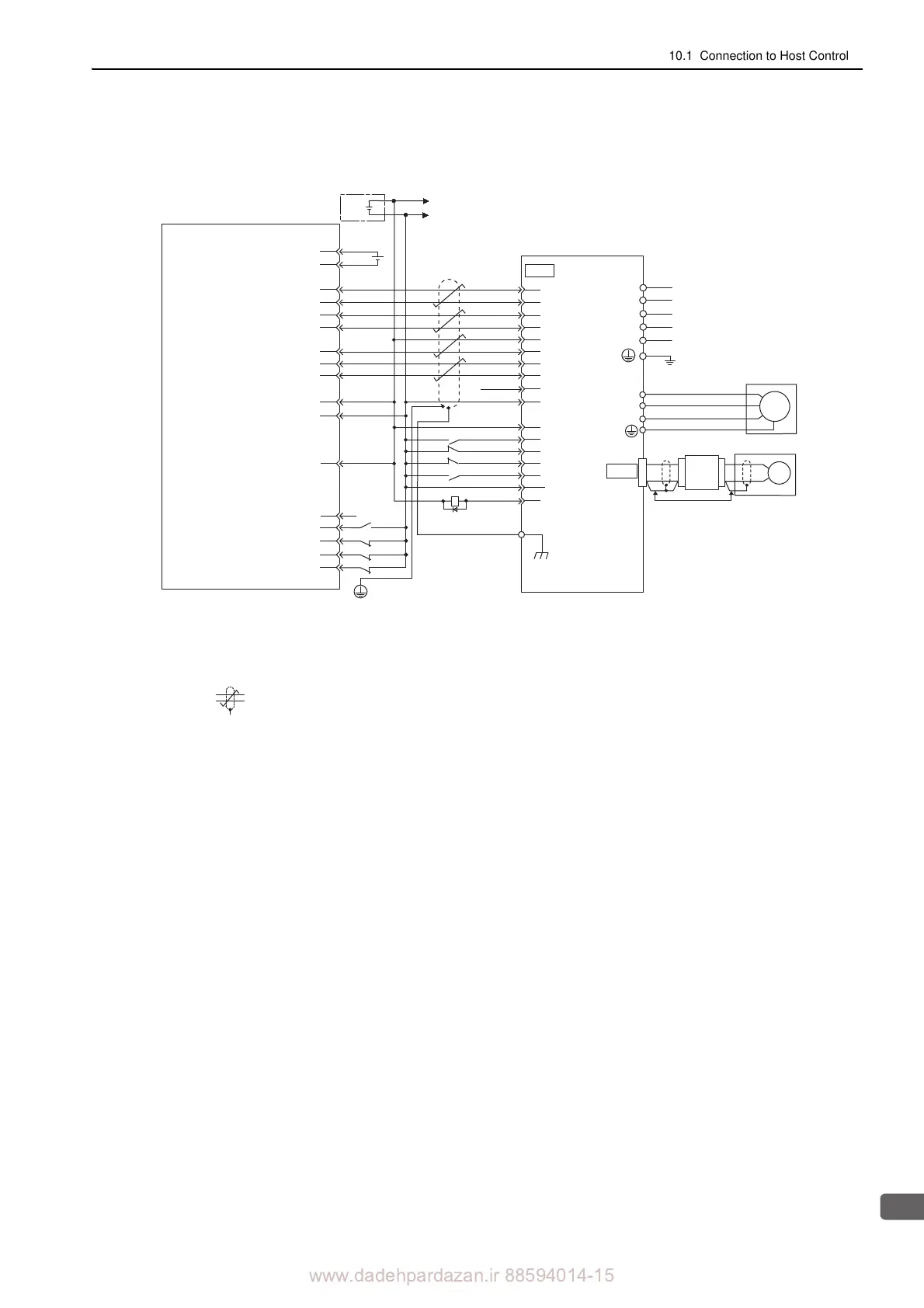
10.1.4 Connection to OMRON’s Position Control Unit
The ALM signal is output for about five seconds after the control power is turned ON. Take this into consideration
when designing the power ON sequence. Also, use the ALM signal to actuate the alarm detection relay 1Ry to stop
the main circuit power supply to the SERVOPACK.
Set parameter Pn200.0 to "
1."
Connect the shielded wire to the
connector shell.
represents twisted-pair wires.
Note 1. Only the signals related to the SGDV SERVOPACK and the OMRON Position Control Unit are shown in the
diagram.
2. The main circuit power supply is a three-phase 200 VAC SERVOPACK input in the example.
3. Incorrect signal connections will damage the Position Control Unit or SERVOPACK. Wire all connections care-
fully.
4. Open the signal lines not to be used.
5. The above connection diagram shows only X-axis connections. When using other axes, make connections to the
SERVOPACK in the same way.
6. Short-circuit the normally closed (NC) input terminals that are not used at the I/O connector section of the posi-
tion control unit.
7. Make the settings so that the servomotor can be turned ON/OFF by the Servo ON (/S-ON) signal.
8. The SERVOPACK incorporates safety functions to protect people from the hazardous operation of the movable
parts of the machines, reduce the risk, and ensure the safety of the machine in operation. Necessary circuits and
settings are required in CN8 to use these functions. If these functions are not used, use the SERVOPACK with the
enclosed safety jumper connected to CN8. For details, refer to 5.11 Safety Function.
Position Control Unit
manufactured by OMRON Corporation
CS1W-NC133 / 233 / 433
SGDV
SERVOPACK
5-V power supply for pulse output
5-V GND for pulse output
24-V power supply for output
24-V GND for output
CCW(+) output
CCW(-) output
CW(+) output
CW(-) output
Origin input signal
Origin input common
Error counter reset output
X-axis CW limit input
X-axis CCW limit input
X-axis immediate stop input
X-axis external interrupt input
X-axis origin proximity input
Connector
shell
Control
power supply
Main circuit
power supply
I/O power supply
CN1
A3
A5
A6
A7
A4
8
20
25
L1C
L3
L2
L1
L2C
19
12
7
14
15
A16
A11
A14
A1
A2
A8
A20
A22
A23
A21
A19
11
/SIGN
CLR
/CLR
PCO
PULS
/PULS
SIGN
/PCO
COIN+
/COIN-
A24
26
31
32
44
42
43
47
40
+24-V-IN
/S-ON
P-OT
N-OT
/ALM-RST
ALM-
ALM+
1Ry
FG
∗1
∗2
∗3
∗4
+5 V
Input common
+
-
+24 V
0
24
+24
V
CN2
W
V
U
M
Enc
Servomotor
Linear scale
Properly treat the end of
shielded wires.
Serial
converter
unit