www.dadehpardazan.ir 88594014-15
3.3 I/O Signal Allocations
3-23
3.3 I/O Signal Allocations
This section describes the I/O signal allocations.
3.3.1 Input Signal Allocations
In most cases, input signals can be used at the factory settings. Input signals can also be allocated as required.
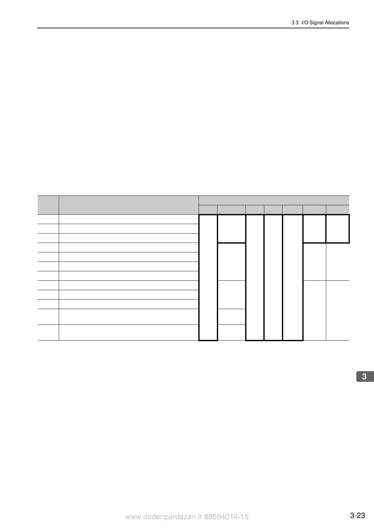
(1) Using Factory Settings
Items in cells with bold lines in the following table are the factory-set signal allocations.
If the control method is changed in Pn000.1, the signals wi
ll function as required for the control method.
The factory-set signal allocations will remain unchanged.
<Example>
When the control method is set to internal set speed control
with a contact reference, i.e., when Pn000.1 is set
to 3, signal /P-CON (CN1-41) will function as /SPD-D, signal /P-CL (CN1-45) as /SPD-A, and signal /N-CL
(CN1-46) as /SPD-B.
Pn000.1
Setting
Control Method Selection
CN1 Pin No.
40 41 42 43 44 45 46
0 Speed control
/S-ON
Uses as
/P-CON
P-OT N-OT
/ALM-
RS
T
/P-CL /N-CL1 Position control
2 Force control
3 Internal set speed control
Uses as
/SPD
-D
Uses as
/SPD-A
Uses as
/SPD-B
4 Internal set speed control Speed control
5 Internal set speed control Position control
6 Internal set speed control Force control
7 Position control Speed control
Uses as
/C-SEL
Uses as
/P-CL
Uses as
/N-CL
8 Position control Force control
9 Force control Speed control
A Speed control Speed control with zero clamp function
Uses as
/Z
CLAMP
B
Position control Position control with reference pulse
inhibit function
Uses as
/INHIBIT