www.dadehpardazan.ir 88594014-15
3 Wiring and Connection
3.3.1 Input Signal Allocations
3-24
Input signal allocation at factory setting can be checked using the parameters Pn50A and Pn50B.
(2) Changing Input Signal Allocations
When changing input signal allocations, set Pn50A.0 to 1 to enable making the changes.
Input signals are allocated as shown in the following table.
Refer to the Interpr
eting the Input Signal Allocation Tables and change the allocations accordingly.
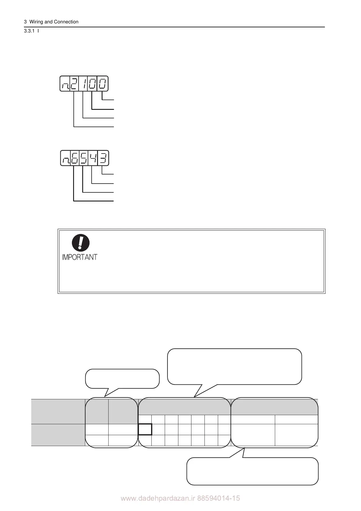
<Interpreting the Input Signal Allocation Tables>
Pn50A
Uses input terminal with factory setting.
Allocates /S-ON signal to CN1-40.
Allocates /P-CON signal to CN1-41.
Allocates /P-OT signal to CN1-42.
Pn50B
Allocates N-OT signal to CN1-43.
Allocates /ALM-RST signal to CN1-44.
Allocates /P-CL signal to CN1-45.
Allocates /N-CL signal to CN1-46.
• Inverting the polarity of the Servo ON, forward run prohibited, and reverse run prohib-
ited signals from the factory setting will prevent the main circuit’s power supply from
bein
g turned OFF or the overtravel function from working in case of signal line discon-
nections or other failures.
If this setting is absolutely necessary, check th
e operation and confirm that there are
no safety problems.
• When two or more signals are allocated to the same input circuit, input signal level is
valid for all allocated signals, resulting in an unexpected machine operation.
CN1 Pin Numbers
40 41 42 43 44 45 46
Pn50A.1
L /S-ON 0123456
HS-ON9ABCDEF
The parameter set values to be used are shown.
Signals are allocated to CN1 pins according to the
selected set values.
Values in cells in bold lines are the factory settings.
Input Signal Names
and Parameters
Connection Not Required
(SERVOPACK judges the connection)
Servo ON
Validity
Level
Input
Signal
87
Always ON Always OFF
If always ON (7) or always OFF (8) is set, signals
will be processed in the SERVOPACK, which will
eliminate the need for wiring changes.
Level at which input signal
allocations are valid.