www.dadehpardazan.ir 88594014-15
3 Wiring and Connection
3.4.2 Sequence Input Circuit
3-32
3.4.2 Sequence Input Circuit
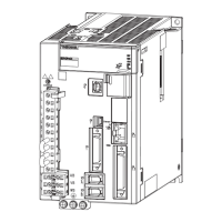
(1) Photocoupler Input Circuit
CN1 connector terminals 40 to 47 are explained below.
The sequence input circuit interface is connected through a relay or op
en-collector transistor circuit. When
connecting through a relay, use a low-current relay. If a low-current relay is not used, a faulty contact may
result.
Note: The 24 VDC external power supply capacity must be 50 mA minimum.
For SEN input signal circuit, refer to 5.9.1 Absolute Data Request Signal (SEN).
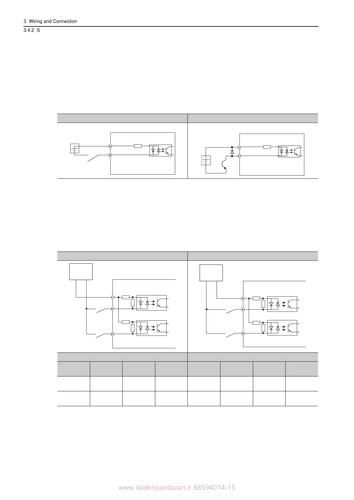
The SERVOPACK’s input circuit uses bidirectional photocoupler. Select either the sink circuit or the source
circuit according to the specifications required for each machine.
Note: The connection examples in 3.2.3 to 3.2.5 show sink circuits.
• The ON/OFF polarity differs between when a sink circuit is connected and when a source circuit is connected.
Relay Circuit Example Open-collector Circuit Example
Sink Circuit Source Circuit
Input Signal Polarities Input Signal Polarities
Signal Level
Voltage
Level
Contact Signal Level
Voltage
Level
Contact
ON
Low (L)
level
0 V Close ON
High (H)
level
24 V Close
OFF
High (H)
level
24 V Open OFF
Low (L)
level
0 V Open
3.3 kΩ
/S-ON, etc.
SERVOPACK
24 VDC
+24 VIN
24 VDC
3.3 kΩ
/S-ON, etc.
SERVOPACK
+24 VIN
24 V
+
−
SERVOPACK input