www.dadehpardazan.ir 88594014-15
3.2 I/O Signal Connections
3-17
3.2 I/O Signal Connections
This section describes the names and functions of I/O signals (CN1). Also connection examples by control
method are shown.
3.2.1 I/O Signal (CN1) Names and Functions
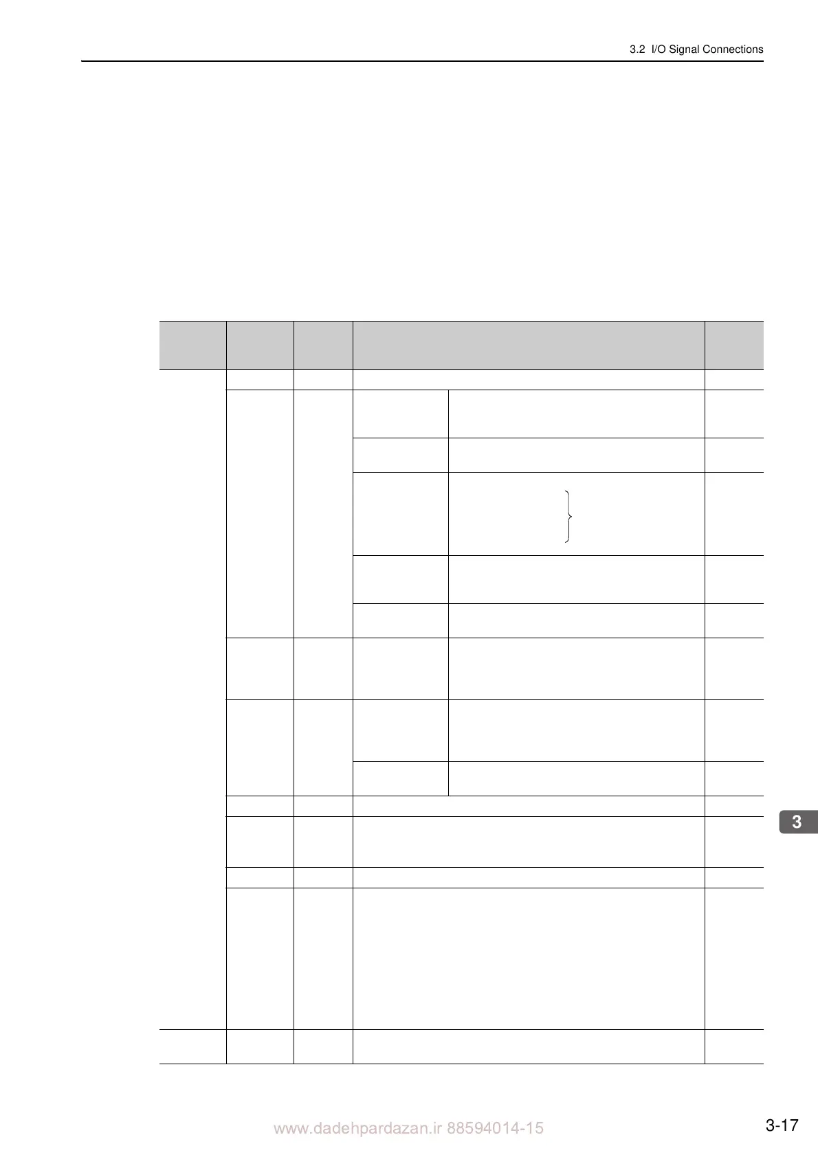
The following table shows the names and functions of I/O signals (CN1).
(1) Input Signals
Control
Method
Signal
Name
Pin No. Function
Refer-
ence
Section
Common
/S-ON 40 Servo ON/OFF: Turns ON/OFF the servomotor. 5.2.1
/P-CON 41
Proportional con-
trol reference
Switches the speed control loop from PI (propor-
tional/integral) to P (proportional) control when
ON
.
6.9.4
Movement Direc-
tion reference
With internal set speed control selected: Switches
the servomotor movement direction.
5.6.1
Control switch-
ing
5.7.2
Zero-clamp refer-
ence
With speed control with zero-clamp function
selected:
Reference speed is zero when ON.
5.3.5
Reference pulse
block
With position control with
reference pulse stop
selected: Stops reference pulse input when ON.
5.4.8
P-OT
N-OT
42
43
Forward run
prohibited,
Reverse run
prohibited
With overtravel prevention: Stops servomotor
when movable
part travels beyond the allowable
range of motion.
5.2.4
/P-CL
/N-CL
45
46
Forward external
forc
e limit,
Reverse external
forc
e limit
Activates/deactivates external force limit func-
tion.
5.8.2
5.8.4
Internal set speed
switching
With internal set speed control selected: Switches
the internal set speed settings.
5.6.1
/ALM-RST 44 Alarm reset: Releases the servo alarm state.
+24VIN 47
Control power supply input for sequence signals.
Allowable voltage range: 11 to 25 V
Note: The 24 VDC power supply is not included.
3.4.2
SEN 4 (2) Initial data request signal when us
ing an absolute linear scale. 5.9.1
/SPD-D
/SPD-A
/SPD-B
/C-SEL
/ZCLAMP
/INHIBIT
/P-DET
/G-SEL
/PSEL
Signals
t
hat can
be allo-
cated
The following input signals can be
changed to allocate functions:
/S-ON, /P-CON, P-OT, N-OT, /P-CL, /N-CL, and /ALM-RST.
3.3.1
5.3.5
5.4.3
5.4.8
5.6.1
5.7.1
6.8.1
Speed V-REF 5 (6) Inputs speed reference. Input voltage range: 12 V max.
5.3.1
5.5.4
Position speed
Position force
Force speed
Enables control switching.