www.dadehpardazan.ir 88594014-15
8 Monitor Displays (Un)
8.7.2 Interpreting Output Signal Display Status
8-10
8.7.2 Interpreting Output Signal Display Status
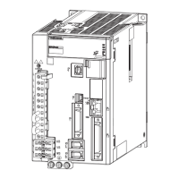
The status of allocated signals is displayed on the 7-segment display on the panel operator.
Output terminals correspond to LED numbers as shown in the following table.
• When the output signal is in OFF status, the top segment (LED) is lit.
• When the output signal is in ON status, the bottom segment (LED) is lit.
Note: Input signals use the following circuit configuration.
• OFF: Transistor OFF
• ON: Transistor ON
Example
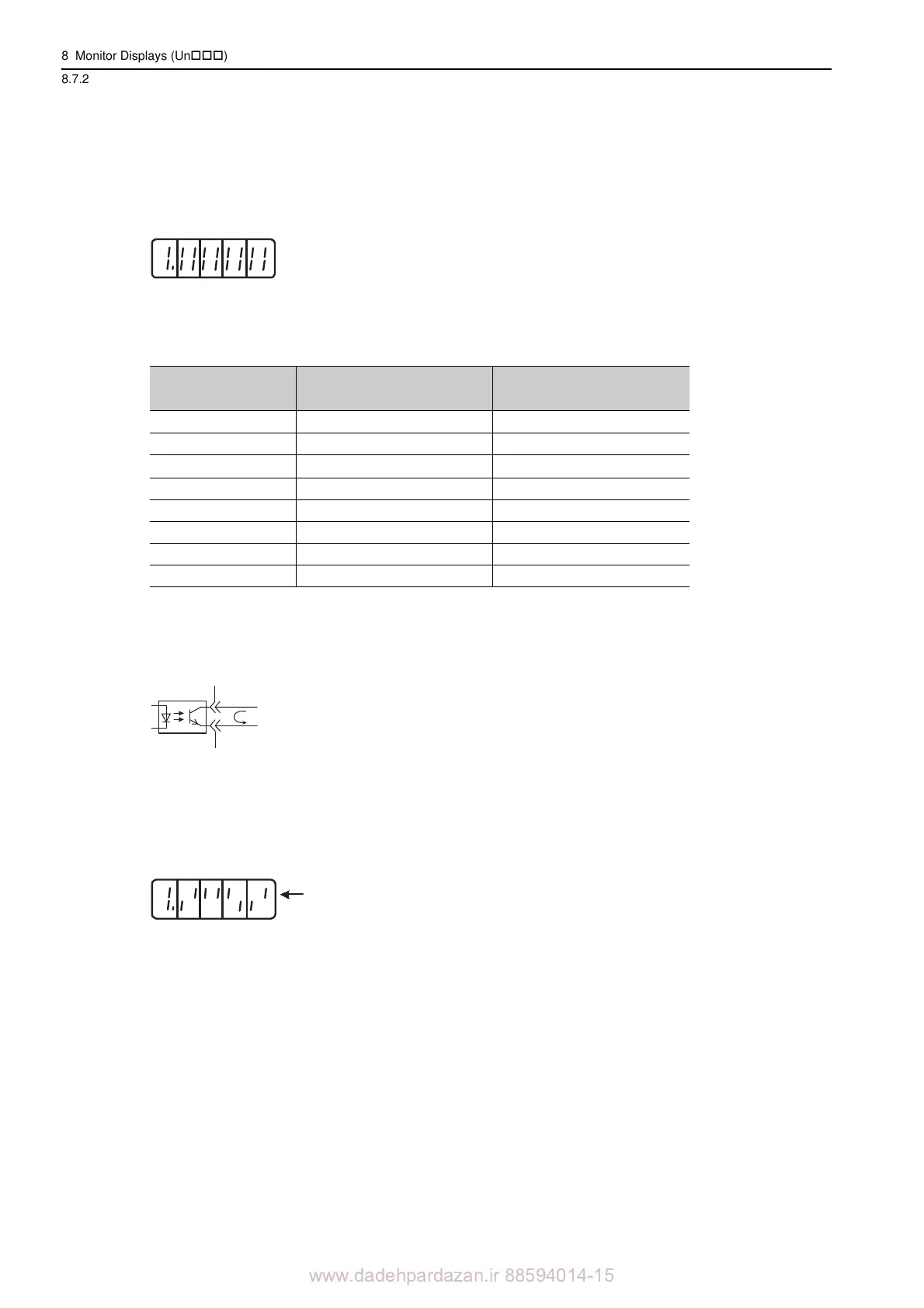
8.7.3 Output Signal Display Example
Output signals are displayed as shown below.
• When the ALM signal is OFF
Display LED
Number
Output Terminal Name
Signal Name
(Factory Setting)
1
CN1-31
,
-32
ALM
2 CN1-25, -26 /COIN or /V-CMP
3
CN1-27,
-28
/TGON
4 CN1-29, -30 /S-RDY
5 CN1-37 ALO1
6 CN1-38 ALO2
7 CN1-39 ALO3
8 Reserved
4 321
Top: OFF
Bottom: ON
Number
6 785
ON: Transistor ON
The top segment of
number 1 is lit.
76854321